
The Anatomy of a 3way Switch Circuit
When undertaking a home electrical upgrade, wiring a 3way switch is one of the most common yet frequently misunderstood projects. Unlike a standard single-pole switch that simply breaks a single hot wire, a 3way circuit allows you to control a single lighting load from two distinct physical locations—such as the top and bottom of a stairwell, or at either end of a long hallway. To execute this safely and correctly, you must understand the internal anatomy of the switch itself.
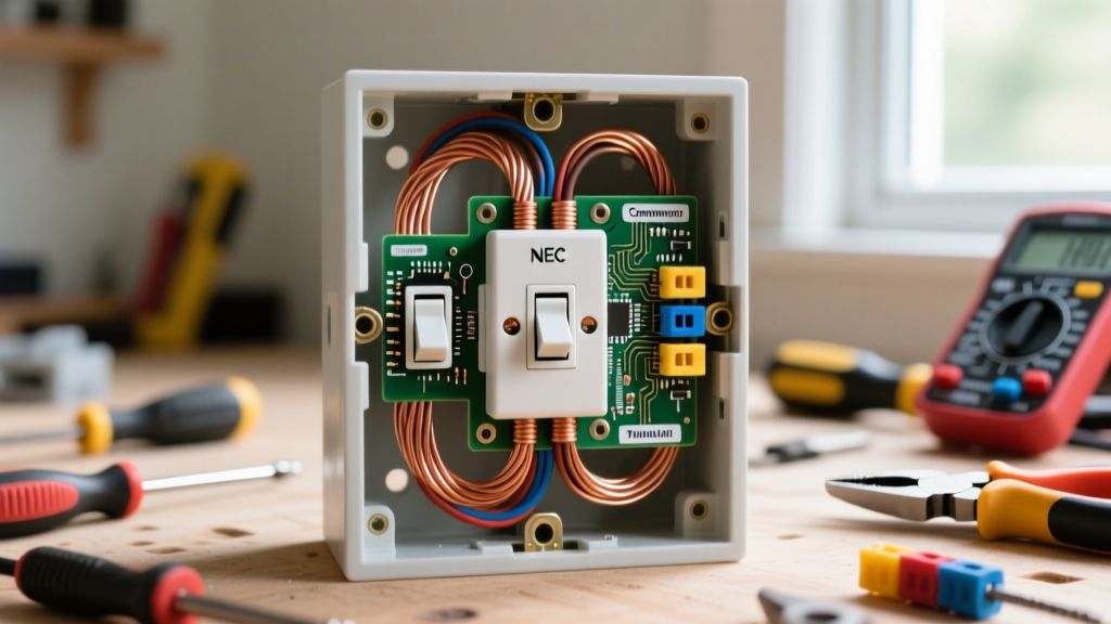
A standard 3way switch, such as the widely used Leviton Decora 15A 3-Way Switch (5603-2W), features three primary terminals (excluding the bare copper ground). The most critical terminal is the Common terminal, typically identified by a darker, blackened, or copper-colored screw. This terminal is the pivot point of the internal mechanism; it connects to either one of the two Traveler terminals, which are identified by lighter brass-colored screws. Understanding this mechanical toggle is the key to correctly routing your line, load, and traveler wires.
Defining the Circuit Roles
- Line (Hot): The continuous 120V power feed originating directly from your electrical panel's breaker.
- Load (Switched Hot): The wire that carries power from the switch system to the light fixture.
- Travelers: The two wires that run between Switch 1 and Switch 2, carrying the alternating hot current based on the toggle position.
- Neutral: The return path to the panel. Historically, neutrals were not required at the switch boxes, but modern code has changed this.
The NEC Neutral Requirement: A Crucial Code Update
Before you pull any new wire, you must be aware of the National Electrical Code (NEC) Article 404.2(C). As detailed in the NFPA National Electrical Code guidelines, modern installations require a grounded neutral conductor to be present at every switch location. This was implemented to accommodate smart switches, occupancy sensors, and Wi-Fi-enabled dimmers that require a continuous low-voltage standby current to operate their internal radios.
If you are wiring a 3way switch in a new construction or performing a full gut-renovation, you must run 14/3 NM-B cable (for 15-amp circuits) or 12/3 NM-B cable (for 20-amp circuits) between the switches to ensure both travelers and a neutral are present. If you are retrofitting an older home built before 2011, you may encounter legacy 'switch loops' where only a 14/2 cable was run to the switch, using the white wire as a re-identified hot. While grandfathered for standard mechanical switches, this will prevent you from installing modern smart 3way systems without pulling new wire.
Essential Tools and Material Costs
Success in wiring a 3way switch relies heavily on proper diagnostic tools. Guessing which wire is the line and which is the load is a primary cause of short circuits and breaker trips. Below is a breakdown of the specific tools and materials required for a standard 15-amp residential lighting circuit.
| Item | Specific Model / Type | Estimated Cost | Purpose |
|---|---|---|---|
| Voltage Tester | Klein Tools NCVT-2 | $22.00 | Verifies absence of voltage on 12-700V AC circuits before touching bare copper. |
| Digital Multimeter | Fluke 117 True-RMS | $190.00 | Essential for identifying the Line vs. Load by measuring voltage to ground. |
| Cable | Southwire 14/3 NM-B Romex | $0.45 / ft | Carries the two travelers and the neutral between the two switch boxes. |
| Wire Connectors | Ideal WingNut 341 (Tan) | $8.00 / 50pk | Secures multiple 14 AWG wires together in deep junction boxes. |
| Switches | Leviton 5603-2W (15A) | $4.50 ea | Standard residential 3way toggle or Decora rocker switch. |
Phase 1: Power Verification and Wire Identification
The most daunting aspect of wiring a 3way switch is staring into a wall box filled with six or more wires and determining their origins. Never rely on wire color alone in an existing installation, as previous homeowners or electricians may have deviated from standard color coding.
The Multimeter Line/Load Test
- Isolate the Circuit: Turn off the breaker and use your Klein Tools NCVT-2 to verify that all wires in both switch boxes are completely dead.
- Expose the Copper: Ensure you have a known, bare copper ground wire accessible in the box.
- Restore Power Safely: Turn the breaker back on. Warning: Do not touch bare wire ends during this step.
- Measure to Ground: Set your multimeter to AC Voltage. Place the black probe on the bare copper ground and the red probe on each black wire in the box.
- Identify the Line: The wire that reads a continuous 120V (±5V) regardless of the light's status is your Line (Hot) feed. This wire connects to the Common (dark) screw on Switch 1.
- Identify the Load: The wire that reads 0V when the circuit is open, but would carry current to the fixture, is your Load. In a standard layout where power hits Switch 1 first, the Load wire is actually one of the travelers heading to Switch 2. If power hits the light fixture first and drops down to the switches, the wire heading back up to the light is your Load and connects to the Common screw on Switch 2.
Phase 2: Routing the Travelers and Switch Loops
Once the Line and Load are identified and secured to their respective Common screws, you must route the travelers. The travelers are the two wires that physically connect the brass screws of Switch 1 to the brass screws of Switch 2.
Pro-Tip on Traveler Miswiring: Because the travelers are interchangeable, you cannot wire them 'backward' in terms of circuit logic. If you swap Traveler A and Traveler B on the brass screws, the circuit will still function perfectly. The only time a 3way circuit fails is when a traveler is accidentally placed on the Common screw, or the Line/Load is placed on a brass traveler screw.
When dealing with a Switch Loop (where power from the panel enters the ceiling fixture box first, and a single cable drops down to the wall switch), the NEC requires you to re-identify the white wire of a 14/2 cable as a hot line. You must wrap the white wire in black electrical tape or use black heat shrink at both ends. This signals to future electricians that the white wire is acting as a permanent hot or switched hot, not a neutral.
Troubleshooting Common 3way Failure Modes
Even experienced DIYers encounter issues when wiring a 3way switch. If your newly wired circuit isn't functioning, consult this diagnostic matrix before tearing open the drywall.
| Symptom | Probable Failure Mode | Corrective Action |
|---|---|---|
| Light works from Switch A, but Switch B does nothing. | Switch B's Common screw is wired to a Traveler, or Switch A's Line is on a brass screw. | Re-test Line/Load with a multimeter. Ensure the continuous hot is on the dark Common screw of the first switch in the chain. |
| Light only turns on if both switches are in the 'Up' position. | Traveler wires are crossed or misidentified between the two boxes. | Verify continuity between the brass screws of Switch A and Switch B using a multimeter's ohmmeter setting (power off). |
| Breaker trips immediately upon flipping either switch. | Dead short. A hot traveler is touching a bare ground wire, or the neutral is bonded to the ground at the fixture. | Inspect the fixture box. Ensure the white neutral from the panel only connects to the fixture's white wire, and never to the switch's ground pigtail. |
| Smart 3way switch will not power on or connect to Wi-Fi. | Missing neutral wire in the switch box (pre-2011 wiring). | You must pull a new 14/3 cable to provide a dedicated neutral to the smart switch's internal power supply. |
Final Safety and Torque Checks
Before installing the switch into the drywall box, give every wire a firm tug to ensure it is seated under the screw head. Loose connections cause arcing, which is a leading cause of residential electrical fires. If you are using back-wire (push-in) terminals, ensure the wire is stripped to the exact length specified by the manufacturer's gauge on the back of the device—usually 1/2 inch. Once the switches are mounted, use a receptacle tester or a simple lamp to verify the 3way logic from both locations. Mastering the process of wiring a 3way switch not only adds convenience to your home but significantly builds your foundational knowledge of residential electrical theory.