
The Anatomy of a YoRadio Vintage Dial Retrofit
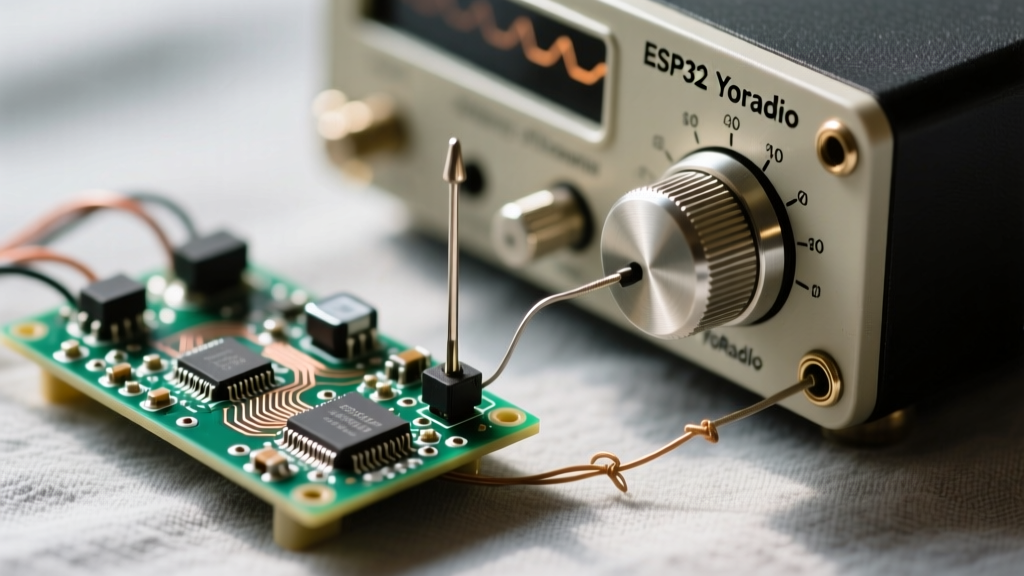
Retrofitting a mid-century American tube radio with modern internet streaming capabilities is a pinnacle DIY achievement. When integrating an ESP32 running the popular YoRadio firmware into a US vintage case—such as a 1950s Zenith Trans-Oceanic or a Philco Predicta—the physical tuning needle becomes the focal point of the build. Unlike modern digital displays, the analog glass dial requires mechanical actuation, usually driven by a servo or stepper motor mapped to the rotary encoder.
However, merging high-frequency Wi-Fi streaming with delicate mechanical linkages introduces a host of unique failure modes. If your ESP32 YoRadio US vintage case tuning needle is jittering, slipping, or introducing audio hum into your I2S DAC, this comprehensive troubleshooting guide will help you isolate and resolve the exact hardware and software bottlenecks.
Diagnosing Physical Tuning Needle Failures
The mechanical linkage in US vintage radios relies on a continuous loop of dial cord wrapped around a tuning capacitor pulley and a tensioning spring. When adapting this for an ESP32, makers typically 3D-print a custom spool that attaches to a servo horn, replacing the original variable capacitor shaft.
Dial String Slack and Pulley Slip
The most common cause of a lagging or slipping tuning needle is the use of incorrect cord material. Original 1940s radios used waxed cotton string, which stretches and rots over time. For a servo-driven YoRadio build, cotton is entirely unsuitable due to the high-torque micro-adjustments of digital servos.
- The Fix: Replace the cord with 0.6mm to 0.8mm braided Dyneema (UHMWPE) fishing line. Dyneema has near-zero stretch under the low-tension loads of a dial needle.
- Tensioning: US chassis designs often use a small S-hook spring to maintain tension. If your 3D-printed spool lacks a groove to keep the Dyneema centered, the string will bunch up and slip. Ensure your spool design includes a 1.5mm deep V-groove and use a 5x20mm extension spring to maintain exactly 150-200 grams of tension.
Mechanical Binding in US Zenith/Philco Chassis
Vintage US chassis often feature heavy brass idler wheels and felt washers that have petrified over the decades. If the servo stalls or the needle stutters at specific points on the dial, the mechanical resistance is likely exceeding the servo's stall torque. Disassemble the dial mechanism, clean the brass shafts with isopropyl alcohol, and apply a synthetic clock oil or PTFE-based dry lubricant. Avoid standard WD-40, which will attract dust and gum up the linkage.
Resolving ESP32 PWM Jitter and Servo Noise
If your tuning needle vibrates or 'jitters' while the radio is streaming audio, you are experiencing a classic ESP32 peripheral conflict. YoRadio relies heavily on the Wi-Fi radio to buffer audio streams. The ESP32's default PWM peripheral, known as LEDC (LED Control), uses a sigma-delta modulation technique that is highly susceptible to Wi-Fi interrupt latency.
The LEDC vs. MCPWM Driver Conflict
When a Wi-Fi packet arrives, the ESP32 pauses the LEDC timer to handle the network interrupt. This causes micro-delays in the PWM pulse width sent to your servo, which the servo interprets as a command to move slightly, resulting in a shaking needle.
Expert Tip: Never use the standard Arduino
Servo.hor basicledcWrite()functions for precision analog dials on the ESP32. The Wi-Fi stack will always corrupt the signal timing.
The Fix: Transition your servo control to the ESP32's MCPWM (Motor Control Pulse Width Modulation) peripheral. MCPWM operates on a dedicated hardware state machine that is completely immune to Wi-Fi and FreeRTOS task interrupts. Alternatively, offload the PWM generation entirely by using an I2C PCA9685 16-channel PWM driver board, which generates the servo pulses on its own dedicated crystal oscillator.
Isolating the I2S DAC from Servo Ground Loops
A secondary symptom of servo integration is a loud 'buzz' or 'pop' in the audio output every time the tuning needle moves. This occurs because servos like the MG996R can draw up to 1.5A during startup. This massive current spike causes 'ground bounce' on the ESP32's ground plane, which directly injects noise into the sensitive analog ground of your PCM5102A or MAX98357A I2S DAC.
To resolve this, implement a Star Grounding topology. Run a dedicated ground wire from the power supply directly to the servo, and a separate ground wire to the ESP32/DAC. Furthermore, power the servo using a dedicated LM2596 buck converter stepped down to 5V, rather than sharing the ESP32's onboard 5V regulator. Place a 470µF electrolytic capacitor and a 0.1µF ceramic capacitor in parallel across the servo's power rails to absorb transient current spikes.
YoRadio Firmware Mapping and Calibration
Once the hardware is stabilized, the ESP32 YoRadio US vintage case tuning needle must be accurately mapped in software so that the physical dial matches the digital station list or volume levels.
YoRadio handles rotary encoders and servo mapping through its web configuration interface and the settings.h file. If your needle sweeps past the physical glass boundaries or fails to reach the ends of the dial, you need to calibrate the servo limits.
- Define Physical Limits: In the YoRadio web UI, navigate to the Hardware/Controls section. Set the 'Servo Min' and 'Servo Max' PWM values. Do not rely on the default 0 and 180-degree assumptions; measure the exact pulse width (in microseconds) required to park the needle at the far-left (e.g., 88 MHz) and far-right (e.g., 108 MHz) markers on your specific US vintage glass.
- Encoder Step Mapping: US vintage dials are often non-linear. If you are using a standard 24-step rotary encoder, map the encoder steps to a logarithmic curve in the firmware if you are controlling volume, or a linear array if you are scrolling through an array of internet station URLs.
- Debounce the Encoder: Mechanical bounce from cheap rotary encoders will cause the needle to jump erratically. Implement a 10ms software debounce in the encoder interrupt routine, or add 0.1µF ceramic capacitors across the encoder pins and ground to filter hardware noise.
Troubleshooting Matrix: Symptoms to Solutions
| Symptom | Root Cause | Corrective Action |
|---|---|---|
| Needle vibrates constantly during Wi-Fi streaming | LEDC PWM interrupt latency caused by Wi-Fi stack | Switch to MCPWM peripheral or use an I2C PCA9685 driver |
| Needle slips or fails to track encoder turns | Dial string stretch or 3D-printed spool groove failure | Use 0.6mm braided Dyneema line; add a V-groove to the spool |
| Loud audio hum/popping when needle moves | Servo current spike causing I2S DAC ground bounce | Implement star grounding; use a separate 5V buck converter for servo |
| Needle hits physical glass stops before software limits | Default 0-180 degree servo mapping mismatch | Calibrate exact microsecond PWM limits in YoRadio Web UI |
| Erratic needle jumps without touching the encoder | Electromagnetic interference (EMI) on encoder lines | Add 0.1µF decoupling caps to encoder pins; enable software debounce |
Final Bench Testing Protocol
Before permanently mounting the ESP32 and servo into the US vintage case, perform a 24-hour bench burn-in. Run YoRadio continuously, cycling through at least 10 different internet radio stations while simultaneously sweeping the tuning needle from end to end every 5 minutes via an automated script or manual testing. Monitor the ESP32's core temperature and check for any Wi-Fi disconnects. For further insights on managing I2S audio stability alongside mechanical peripherals, refer to the ESP32-audioI2S repository documentation, which details memory allocation strategies that prevent audio stuttering during heavy servo actuation.
By addressing the mechanical realities of vintage US chassis designs and respecting the ESP32's hardware peripheral limitations, your YoRadio tuning needle will operate with the smooth, fluid precision that a classic piece of radio history deserves.