
The Unspoken Rules of ESP32 WROOM Hardware
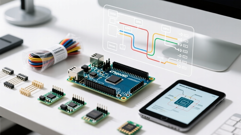
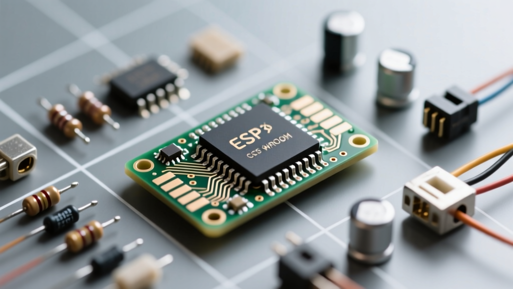
The Espressif ESP32 WROOM module revolutionized the maker community by offering dual-core processing, Wi-Fi, and Bluetooth at an unbeatable price point. However, beneath the surface of the Arduino IDE and ESP-IDF lies a complex silicon architecture with well-documented hardware quirks. For engineers and advanced makers, understanding the ESP32 WROOM errata is not just an academic exercise—it is the difference between a prototype that works on a desk and a product that survives in the field.
This community-driven resource aggregates the most critical silicon bugs, architectural limitations, and peripheral conflicts found in the original ESP32 (including ECO0 through v3.1 revisions). We bypass the basic tutorials and dive straight into the failure modes, providing actionable workarounds derived from thousands of hours of collective field testing.
Critical Silicon Errata and Community Workarounds
While later chip revisions (like the ESP32-D0WD-V3) resolved many early silicon bugs, certain architectural decisions remain permanent fixtures of the original WROOM series. Below are the most common traps that catch developers off guard.
1. The ADC2 vs. Wi-Fi Collision
One of the most frequently misunderstood limitations in the ESP32 ecosystem is the conflict between the second Analog-to-Digital Converter (ADC2) and the Wi-Fi radio. The ESP32 features two Successive Approximation Register (SAR) ADCs. While ADC1 is dedicated to general-purpose analog reading, ADC2 is hardware-multiplexed with the Wi-Fi MAC layer. The Wi-Fi subsystem uses ADC2 internally for RF power calibration and monitoring.
The Failure Mode: When you call WiFi.begin() in your Arduino sketch, the FreeRTOS Wi-Fi driver seizes exclusive control of ADC2. Any subsequent calls to analogRead() on ADC2 pins (GPIO 0, 2, 4, 12, 13, 14, 15, 25, 26, 27) will fail silently or return garbage data.
The Workaround: Design your PCB to route all analog sensors to ADC1 pins (GPIO 32, 33, 34, 35, 36, 39). If you absolutely must read an analog value while Wi-Fi is active, you must temporarily disable the Wi-Fi modem, read the ADC2 pin, and re-enable the modem—a process that introduces unacceptable latency for most real-time applications. For deep technical context, refer to the official Espressif ADC API Documentation.
2. I2C Peripheral Lockups and the STOP Condition Bug
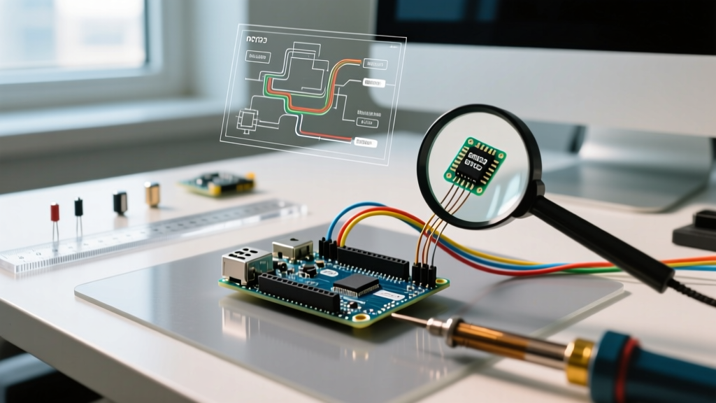
The ESP32 hardware I2C controller is a complex state machine. In early silicon revisions (ECO0 and ECO1), a severe erratum existed where the I2C peripheral would fail to issue a STOP condition if the bus experienced noise or if a slave device stretched the clock unexpectedly.
The Failure Mode: If a noise spike corrupts the SDA line during the 9th clock pulse (the ACK/NACK phase), the hardware state machine can become trapped in a WAIT_ACK state. The SCL line remains high, the bus is locked, and the Wire.h library hangs indefinitely, requiring a hard power cycle to recover.
The Workaround: The community has developed several robust defenses against this:
- Software Reset Routine: Implement a watchdog timer that detects I2C timeouts. Upon timeout, call
i2c_driver_delete()and reinitialize the peripheral. - Bus Clearing Sequence: Manually toggle the SCL pin as a GPIO output 9 times to force the slave device to release the SDA line, then reinitialize the hardware I2C driver.
- Software I2C: For mission-critical sensors, use a software bit-banged I2C library. While slower, it bypasses the flawed hardware state machine entirely.
3. Deep Sleep Strapping Pin Traps (GPIO12 & GPIO15)
The ESP32 uses specific GPIOs as 'strapping pins' to determine boot modes and flash voltages during the reset sequence. GPIO12 (MTDI) is particularly dangerous for makers designing custom carrier boards.
The Failure Mode: GPIO12 dictates the internal VDD_SDIO LDO voltage. If pulled HIGH during boot, the ESP32 configures the LDO to output 1.8V for the SPI flash. However, 99% of commercial WROOM modules utilize 3.3V SPI flash. If your circuit pulls GPIO12 high (e.g., connecting it to a sensor that outputs a high signal on startup), the chip boots, switches the flash voltage to 1.8V, the flash chip brownouts, and the ESP32 enters an endless bootloop.
The Workaround: Never place external pull-up resistors on GPIO12. If GPIO12 must be used for an external device, ensure the device defaults to a high-impedance state or LOW during the ESP32's boot sequence. For a comprehensive list of boot conflicts, consult the Espressif ESP32 Series Errata Document.
Errata Impact Matrix by Chip Revision
Not all ESP32 WROOM modules are created equal. The silicon revision printed on the metal RF shield dictates which bugs you will face. Below is a community-maintained matrix of how major errata were handled across revisions.
| Silicon Revision | I2C Glitch Bug | ADC2/Wi-Fi Conflict | Deep Sleep Wakeup | Flash Encryption |
|---|---|---|---|---|
| ECO0 / ECO1 | Severe (Requires SW fix) | Present | RTC GPIO leakage | Flawed |
| ECO2 / ECO3 | Mitigated | Present | Fixed | Improved |
| v3.0 (Rev 3) | Hardware Fixed | Present | Fixed | Hardware Fixed |
| v3.1 (Rev 3.1) | Hardware Fixed | Present | Fixed | Hardware Fixed |
Community Insight: The ADC2/Wi-Fi conflict is an architectural reality of the original ESP32 die, not a 'bug' that can be patched via silicon revision. Only the ESP32-S3 and ESP32-C3 architectures resolved this by separating the RF calibration ADC from the user-facing ADC peripherals.
Power Delivery: The 'Phantom' Errata
While not strictly a silicon logic bug, the Brownout Detector (BOD) behavior on the WROOM module is so notoriously unforgiving that the community treats it as a de facto hardware erratum.
The ESP32's internal BOD is calibrated to trigger a system reset if the VDD33 rail drops below approximately 2.43V. During Wi-Fi transmission (TX bursts), the WROOM module can draw transient current spikes upwards of 500mA for brief milliseconds. If your PCB trace impedance is too high, or if you are using a sluggish linear regulator like the AMS1117-3.3 without adequate bulk capacitance, the voltage rail will dip below the BOD threshold.
The Symptom: The ESP32 resets silently without printing a panic code to the serial monitor, often leading developers to believe their code is crashing due to a watchdog timeout or memory leak.
The Fix: Place a 100µF low-ESR tantalum or ceramic capacitor as close to the WROOM module's VDD and GND pins as physically possible. Furthermore, use the ESP-IDF function esp_brownout_init() or adjust the BOD threshold via the RTC_CNTL_BROWN_OUT_REG register if your power supply is marginally undersized but stable enough to sustain the RF envelope.
Designing Around the Quirks: A Maker's Checklist
Before sending your ESP32 WROOM carrier board to fabrication, run through this community-vetted checklist to ensure you have designed around the silicon errata:
- Pin Assignment Audit: Verify that no analog sensors are routed to ADC2 pins if Wi-Fi or Bluetooth is enabled in your firmware.
- Strapping Pin Isolation: Ensure GPIO0, GPIO2, GPIO12, and GPIO15 are free of external pull-ups that conflict with the bootloader's expected states.
- I2C Pull-up Sizing: Do not rely on the ESP32's internal weak pull-ups for I2C. Use external 4.7kΩ resistors to 3.3V to ensure fast edge transitions and prevent the hardware state machine from misinterpreting noise as data.
- TX Power Throttling: If operating on a tight power budget (e.g., a 500mA USB supply), use
WiFi.setTxPower(WIFI_POWER_11dBm)to cap the RF transmission power, drastically reducing transient current spikes and preventing BOD resets. - Serial Debugging on Boot: Remember that GPIO1 and GPIO3 (Hardware UART0) will output bootloader garbage data at 74880 baud during a hard reset. If your downstream peripheral misinterprets this as a command, use the alternative UART pins (UART1 or UART2) mapped to different GPIOs.
Final Thoughts on Silicon Reality
The ESP32 WROOM remains a powerhouse for IoT and DIY electronics, but it demands respect for its hardware boundaries. By treating the ESP32 WROOM errata not as roadblocks, but as a map of the silicon's physical reality, you can design robust, fault-tolerant systems. Always cross-reference your specific module's revision against the latest Espressif ESP-IDF GitHub Issues tracker, as the community continues to uncover edge-case interactions between the RTOS and the underlying hardware peripherals.