
Diagnostic 1: Boot Loops and 'Failed to Connect' Errors
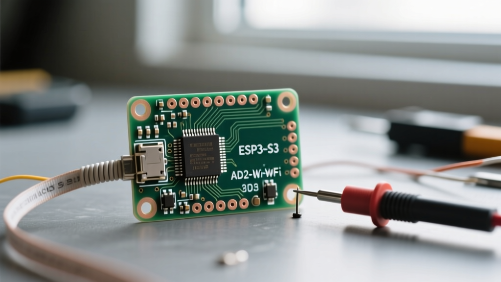
The ESP32-S3 is a massive upgrade over the original ESP32, featuring vector instructions for AI and native USB OTG. However, migrating your wiring to the new esp32-s3 pinout often results in immediate boot failures or IDE upload errors. The most common culprit is the mismanagement of strapping pins.
The Strapping Pin Matrix
Unlike standard GPIOs, strapping pins dictate the chip's boot behavior. If you wire a relay, sensor, or pull-down resistor to these pins incorrectly, the ESP32-S3 will enter the wrong boot mode or fail to execute your sketch.
- GPIO0 (SPI Boot Mode): Must be HIGH during reset for normal SPI flash boot. If pulled LOW, the chip enters ROM serial bootloader. Fix: Ensure no external sensors are pulling GPIO0 to ground on startup.
- GPIO3 (SPI Flash Source): Dictates the SPI flash power source. Usually left floating or pulled HIGH.
- GPIO45 (VDD_SPI Voltage): This is the most dangerous pin for hardware damage. If GPIO45 is pulled HIGH during boot, the internal VDD_SPI regulator outputs 1.8V instead of the default 3.3V. If your SPI flash or PSRAM requires 3.3V, the board will brownout continuously. Fix: Never use GPIO45 for output devices that might toggle during the reset phase.
- GPIO46 (Boot Log): Selects the log printing source. Default is LOW (UART0).
Pro Tip: If your Arduino IDE throws a 'Fatal error: Failed to connect to ESP32-S3: Timed out waiting for packet header', manually hold the BOOT button (GPIO0) while pressing the RST button to force the ROM bootloader, then release RST followed by BOOT.
Diagnostic 2: Analog Readings Fail When Wi-Fi Connects
A frequent troubleshooting ticket we see at Electrical Flux involves makers reporting that their analog sensors work perfectly until Wi-Fi initializes. This is not a software bug; it is a hardware architecture limitation tied directly to the esp32-s3 pinout.
The ADC2 and Wi-Fi Coexistence Conflict
The ESP32-S3 features two Analog-to-Digital Converters: ADC1 and ADC2. ADC1 pins (GPIO1 through GPIO10) are dedicated to analog reading. However, ADC2 pins (GPIO11 through GPIO20) share internal routing with the Wi-Fi and Bluetooth radio modules.
When you call WiFi.begin(), the RF subsystem takes exclusive control of ADC2. Any subsequent analogRead() calls on ADC2 pins will return garbage data or zero.
The Fix
- Audit your schematic and identify all sensors connected to GPIO11-GPIO20.
- Reroute analog sensors (like potentiometers, LDRs, or MQ gas sensors) exclusively to ADC1 pins (GPIO1-GPIO10).
- Reserve ADC2 pins for digital I/O, PWM, or SPI/I2C communications, which remain unaffected by Wi-Fi.
Diagnostic 3: Serial Monitor Goes Dead After Upload
The ESP32-S3 DevKitC-1 boards often feature a native USB interface directly tied to the microcontroller, bypassing the traditional external UART-to-USB bridge (like the CP2102). This is handled by GPIO19 (D-) and GPIO20 (D+).
Native USB vs. UART Bridge Confusion
If your serial monitor works during the upload phase but goes completely dead the moment your sketch starts running, you have likely overwritten the native USB JTAG pins in your code without initializing the USB CDC (Communication Device Class) interface.
According to the Espressif ESP32-S3 Technical Reference Manual, the USB Serial/JTAG controller operates independently of the standard UART0. To fix serial output loss on native USB boards, you must explicitly enable USB CDC in the Arduino IDE:
- Navigate to Tools > USB CDC On Boot and set it to Enabled.
- Ensure you are not using GPIO19 and GPIO20 for external peripherals. Wiring an I2C OLED or motor driver to these pins will short the USB data lines, potentially damaging the chip's USB PHY and causing your PC to fail to recognize the device entirely.
Master ESP32-S3 Safe Pinout Allocation Table
To prevent wiring disasters, use this reference matrix when designing your PCB or breadboard layout. This table categorizes the GPIOs based on their safety for general-purpose I/O.
| GPIO Range | Primary Function | Safe for General I/O? | Troubleshooting Notes |
|---|---|---|---|
| GPIO0 | Strapping / Boot | No (Input Only) | Must be HIGH for normal boot. Pulled LOW for flashing. |
| GPIO1 - GPIO10 | ADC1 / General I/O | Yes (Highly Safe) | Best pins for analog sensors. Unaffected by Wi-Fi. |
| GPIO11 - GPIO20 | ADC2 / General I/O | Conditional | ADC disabled when Wi-Fi/BT is active. Safe for digital use. |
| GPIO19, GPIO20 | Native USB (D-, D+) | No | Reserved for USB OTG/JTAG. Do not wire external components. |
| GPIO21 - GPIO48 | General I/O / SPI | Yes | Safe for digital outputs, relays, and displays. |
| GPIO45, GPIO46 | Strapping Pins | No | GPIO45 controls VDD_SPI voltage. GPIO46 controls boot log. |
Diagnostic 4: Capacitive Touch Pins Triggering Randomly
The ESP32-S3 introduces an updated capacitive touch sensor architecture compared to the original ESP32. Makers frequently report that touch pins trigger false positives or fail to register touches entirely after migrating code.
Recalibrating Touch Thresholds
The S3 touch sensor relies on measuring the charge time of the internal RC circuit. Environmental factors like 3D printed enclosures, humidity, and breadboard parasitic capacitance drastically alter the baseline.
If your touchRead() values are erratic, implement a dynamic baseline calibration routine in your setup() function rather than relying on hardcoded thresholds. Furthermore, consult the official ESP32-S3 Datasheet to verify that your specific board variant supports touch on the GPIOs you are using, as some system-in-package (SiP) modules route internal flash SPI lines over pins that were traditionally touch-capable on older chips.
For deeper GPIO mapping and peripheral routing, the Random Nerd Tutorials ESP32-S3 Guide provides excellent visual diagrams that complement Espressif's raw datasheets, helping you avoid the most common hardware traps.
Diagnostic 5: I2C Bus Lockups and SPI Flash Collisions
Another frequent issue when navigating the esp32-s3 pinout involves communication bus lockups. Unlike the original ESP32, which had somewhat rigid default I2C pins, the ESP32-S3 allows you to map I2C and SPI to almost any GPIO via the internal GPIO matrix. However, this flexibility introduces new failure modes.
SPI Flash vs. External SPI Peripherals
The ESP32-S3 uses GPIO26 to GPIO32 internally for the embedded SPI flash and PSRAM. These pins are not broken out to the headers on most DevKitC-1 boards, but if you are designing a custom PCB using a raw WROOM-2 module, you must absolutely avoid routing external SPI sensors (like the BME280 or SD card modules) to these pins. Doing so will cause a collision with the internal flash memory, resulting in random core panics and Guru Meditation Errors.
I2C Pull-Up Resistor Requirements
The ESP32-S3's internal pull-up resistors (typically around 45kΩ) are often too weak for reliable high-speed I2C communication, especially when wiring multiple sensors like an MPU6050 and an OLED display on the same bus. If your I2C scanner script hangs or returns random hex addresses, the issue is almost always signal integrity.
- The Fix: Add external 4.7kΩ pull-up resistors to both SDA and SCL lines, tied to the 3.3V rail.
- Safe Default Pins: While you can use any safe GPIO, sticking to GPIO1 (SDA) and GPIO2 (SCL) or GPIO8 (SDA) and GPIO9 (SCL) aligns with most community libraries and reduces configuration overhead in the Arduino Wire library.
By systematically isolating your bus communications from strapping pins and ensuring adequate hardware pull-ups, you eliminate the vast majority of I2C and SPI ghost faults that plague beginners. Always verify your strapping pin states with a multimeter during the first power-on to ensure long-term project stability.