
The Anatomy of an ESP32 Programmer
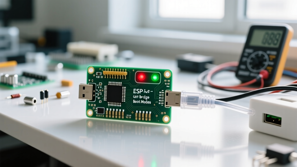
When makers refer to an ESP32 programmer, they are rarely talking about a dedicated, proprietary hardware device like an AVR ISP or a PICkit. Instead, the classic ESP32 (excluding the native-USB S2/S3/C3 variants) relies on a USB-to-UART bridge paired with a clever auto-reset circuit. Understanding this concept is critical for transitioning from plug-and-play development boards to designing custom PCBs or debugging bare modules like the ESP32-WROOM-32E.
At its core, the ESP32 communicates via UART0 (GPIO1 for TX, GPIO3 for RX) during the bootloading phase. A programmer's primary job is to translate your computer's USB signals into 3.3V TTL UART logic. However, translating data is only half the battle. The programmer must also manipulate the ESP32's strapping pins to force it into the ROM bootloader.
The DTR/RTS Auto-Reset Dance
To upload code, the ESP32 must be reset while GPIO0 is held LOW. If you are using a bare module, this means manually pressing and holding a 'BOOT' button, tapping a 'RESET' button, and releasing the 'BOOT' button—a tedious process known as manual bootloading. A proper ESP32 programmer automates this using the UART handshake lines: DTR (Data Terminal Ready) and RTS (Request to Send).
The Transistor Matrix Explained
Development boards like the ESP32 DevKitC use a cross-coupled NPN transistor circuit (typically BC847 or 2N3904) to map DTR and RTS to the EN (CHIP_PU) and GPIO0 pins. The Espressif Hardware Design Guidelines detail this exact schematic to prevent a fatal flaw: pulling both EN and GPIO0 low simultaneously without proper timing, which can cause the chip to latch into an undefined state or brown out.
- State 1 (Idle): RTS=0, DTR=0. EN is HIGH (via pull-up), GPIO0 is HIGH. The chip runs normally.
- State 2 (Boot Prepare): RTS=1, DTR=0. GPIO0 is pulled LOW. EN remains HIGH.
- State 3 (Reset & Boot): RTS=0, DTR=1. EN is pulled LOW (resetting the chip), while GPIO0 remains LOW. When EN releases HIGH, the chip wakes up, reads GPIO0 as LOW, and enters the UART bootloader.
The upload software toggles these pins in milliseconds. If your custom PCB lacks this transistor matrix, your programmer will push data to the UART pins, but the ESP32 will simply ignore it, as it is still running your previous application code.
Onboard UART Bridges vs. Dedicated External Programmers
Not all USB-to-UART bridges are created equal. The choice of silicon on your programmer dictates driver stability, maximum baud rates, and OS compatibility. Below is a comparison of the most common chips found in ESP32 programmers.
| Bridge Chip | Typical Use Case | Max Baud Rate | Driver Complexity | JTAG Support |
|---|---|---|---|---|
| CP2102 / CP2104 | Standard Dev Boards | 3 Mbps | Low (Auto-install) | No |
| CH340G / CH340C | Budget / Clone Boards | 2 Mbps | Medium (Manual Win/Mac) | No |
| FT232RL | Premium External Adapters | 3 Mbps | Low (FTDI Drivers) | No (Bit-bang only) |
| FT2232HL (ESP-Prog) | Professional Debugging | 12 Mbps (UART) | Medium (Zadig/FTDI) | Yes (Native) |
For 90% of hobbyist projects, the onboard CP2102 or CH340C is perfectly adequate. However, if you are programming bare modules on a breadboard, an external FT232RL adapter with a pre-wired DTR/RTS transistor matrix is the most reliable tool in your arsenal.
Stepping Up: JTAG and the ESP-Prog
While UART is sufficient for flashing firmware, it is entirely blind when it comes to debugging. You cannot set hardware breakpoints, inspect real-time memory registers, or step through C++ code line-by-line over a standard serial connection. This is where the ESP-Prog comes in.
The ESP-Prog is Espressif’s official external programmer and debugger, built around the FTDI FT2232HL chip. It provides two distinct channels:
- Channel A (JTAG): Connects to the ESP32’s MTDO, MTCK, MTDI, and MTMS pins, allowing OpenOCD to interface directly with the Xtensa LX6 CPU cores.
- Channel B (UART): Acts as a standard serial bridge for viewing
Serial.print()logs and feeding console commands.
If you are developing complex RTOS applications or debugging hard faults (like Watchdog Timer resets or memory allocation panics), upgrading from a basic UART programmer to a JTAG-capable ESP-Prog is a mandatory leap in your toolchain.
Under the Hood: esptool.py and the SLIP Protocol
Whether you are using the Arduino IDE, PlatformIO, or the ESP-IDF, the actual heavy lifting of programming the ESP32 is handled by an open-source Python utility called esptool.
When the auto-reset circuit triggers the ROM bootloader, the ESP32 listens on UART0 for a specific synchronization sequence. esptool communicates using the SLIP (Serial Line Internet Protocol) framing. It sends commands to read/write SPI flash, verifies checksums, and manages memory mapping. The ROM bootloader, as detailed in the ESP-IDF Bootloader Documentation, resides at address 0x40008000 in the chip's mask ROM, meaning it cannot be bricked or overwritten by a bad sketch.
For advanced users, bypassing the IDE and invoking esptool directly via the command line offers granular control over flash modes (QIO, QOUT, DIO, DOUT) and SPI clock speeds, which is vital when dealing with non-standard external flash chips.
Real-World Troubleshooting: Timed Out Waiting for Packet Header
The most notorious error in the ESP32 ecosystem is the Failed to connect to ESP32: Timed out waiting for packet header message. This means your PC is sending the SLIP sync bytes, but the ESP32's bootloader is not responding. Before blaming a defective chip, evaluate these three common hardware and software failure modes:
1. The EN Pin Capacitor Trap
Expert Insight: Many custom PCB designs mistakenly place a 10µF or 1µF decoupling capacitor directly on the EN (reset) pin to debounce a physical reset button. While this is fine for manual resets, it creates an RC time constant that delays the EN rising edge. By the time the ESP32 actually wakes up,
esptoolhas already released GPIO0, causing the chip to boot into normal execution mode instead of bootloader mode. Fix: Reduce the EN capacitor to 0.1µF or rely entirely on the auto-reset circuit.
2. Strapping Pin Conflicts
GPIO0 is not just a boot-mode selector; it is a general-purpose I/O pin. If your custom circuit ties GPIO0 directly to ground (perhaps to drive an LED or read a switch that happens to be closed), the ESP32 will perpetually enter boot mode and fail to run your code. Conversely, if GPIO0 is pulled HIGH by a strong external circuit during the exact millisecond the auto-reset pulses, the bootloader will be bypassed. Always use a 10kΩ pull-up resistor on GPIO0, and ensure external peripherals do not source or sink significant current during the boot sequence.
3. USB Cable and Port Power Limits
The ESP32 can draw upwards of 350mA during RF transmission spikes. If your USB-to-UART programmer is plugged into an unpowered USB hub, or if you are using a charge-only cable that lacks the D+ and D- data lines, the programming sequence will fail. Furthermore, some cheap CH340G clones suffer from voltage regulator dropout when the ESP32 Wi-Fi radio initializes immediately post-flash, causing the COM port to vanish in the Windows Device Manager. Using a powered USB hub or a high-quality FT232RL programmer eliminates this variable.
Mastering the ESP32 programmer means looking past the USB cable and understanding the intricate dance of UART protocols, strapping pins, and transistor logic. Armed with this knowledge, you can confidently design custom carrier boards, recover bricked modules, and optimize your firmware deployment pipeline.