
The Case for Hardwired IoT: Why Add Ethernet to ESP32?
While the ESP32 is celebrated for its robust Wi-Fi and Bluetooth capabilities, industrial IoT, home automation hubs, and deterministic sensor networks often demand the reliability of a hardwired connection. Integrating an ESP32 with Ethernet eliminates RF interference, provides deterministic latency, and unlocks Power over Ethernet (PoE) capabilities for single-cable deployments.
However, unlike microcontrollers such as the STM32F4 or Teensy 4.1, the standard ESP32 does not have a built-in Ethernet PHY (Physical Layer). To achieve hardwired networking, makers and engineers must choose between two distinct architectural routes: SPI-based controllers or RMII-based PHY transceivers. Understanding the difference is critical for PCB design, throughput expectations, and software stack selection.
Architectural Deep Dive: MAC vs. PHY
To understand how to connect an ESP32 with Ethernet, you must first understand the OSI model layers at play. Network communication requires a MAC (Media Access Control) layer to handle data framing and a PHY (Physical Layer) to handle the electrical signaling over the copper RJ45 cable.
Route A: The SPI Ethernet Controllers (W5500 / ENC28J60)
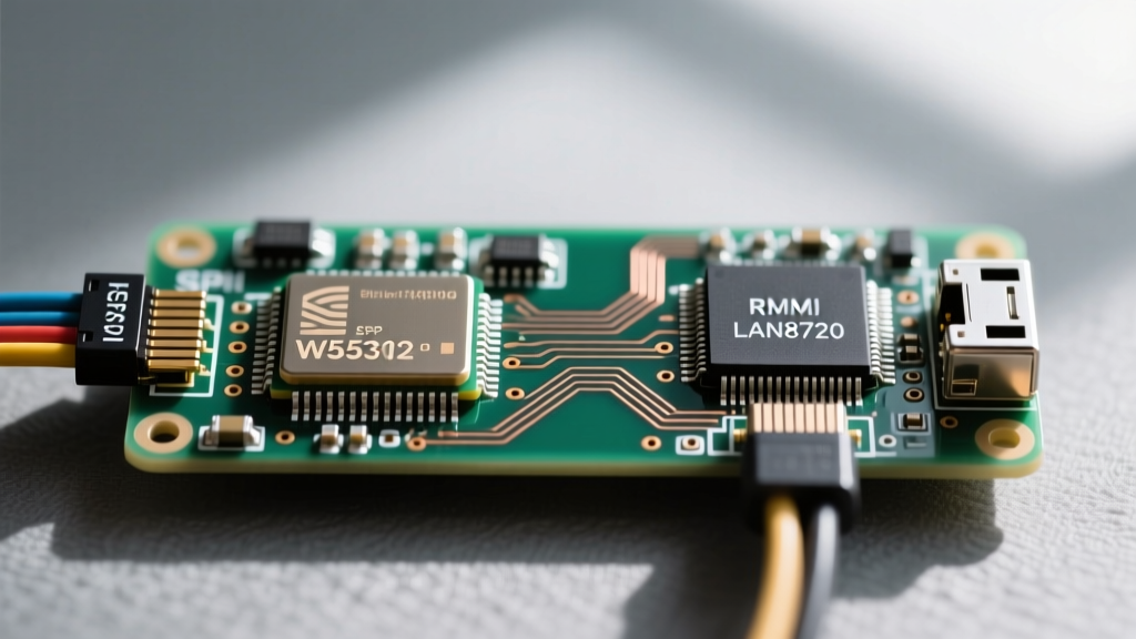
Chips like the Wiznet W5500 contain a built-in MAC, PHY, and a hardware TCP/IP offload engine. The ESP32 communicates with these chips via the SPI bus. In this scenario, the ESP32 is merely passing raw payloads to the W5500, which handles the heavy lifting of TCP/UDP packetization. This is highly reliable but bottlenecks throughput to the SPI bus speed and the chip's internal buffer limits.
Route B: The RMII MAC-PHY Split (LAN8720 / TLK110)
The ESP32 actually possesses an internal Ethernet MAC layer hidden within its silicon. To use it, you must pair the ESP32 with an external PHY-only chip, such as the Microchip LAN8720A. They communicate via the RMII (Reduced Media Independent Interface) protocol. This route leverages the ESP32's native networking stack (lwIP), resulting in vastly superior throughput and lower latency, albeit at the cost of complex pin routing and clock synchronization.
Expert Insight: If your project requires streaming high-frequency telemetry or serving heavy local web dashboards, the RMII route is mandatory. SPI-based Ethernet typically caps out around 30-40 Mbps in real-world Arduino environments, whereas RMII easily sustains 80+ Mbps on the ESP32's 10/100 MAC.
Hardware Comparison Matrix
Selecting the right silicon dictates your firmware architecture. Below is a comparison of the most common chips used to pair an ESP32 with Ethernet.
| Feature | Wiznet W5500 (SPI) | Microchip ENC28J60 (SPI) | Microchip LAN8720A (RMII) |
|---|---|---|---|
| Architecture | MAC + PHY + TCP/IP Stack | MAC + PHY (No TCP/IP Stack) | PHY Only (Uses ESP32 MAC) |
| Interface | SPI (up to 80MHz) | SPI (up to 20MHz) | RMII (50MHz Clock) |
| Max Throughput | ~40 Mbps (Practical) | ~5 Mbps (Practical) | ~90 Mbps (Practical) |
| RAM Offload | 32KB Internal Buffer | 8KB Internal Buffer | Uses ESP32 SRAM/PSRAM |
| Software Stack | Arduino Ethernet.h | UIPEthernet / EthernetENC | ESP-IDF ETH.h |
| Pin Count | 6 Pins (SPI + CS + RST) | 6 Pins (SPI + CS + RST) | 10+ Pins (RMII + MDIO/MDC) |
Wiring the ESP32 with Ethernet: Pinout Realities
The physical wiring is where many makers encounter their first roadblocks. The pin requirements for SPI versus RMII are drastically different.
SPI Pin Mapping (VSPI Default)
Connecting a W5500 module is straightforward. You map it to the ESP32's default VSPI pins:
- MOSI: GPIO 23
- MISO: GPIO 19
- SCK: GPIO 18
- CS (Chip Select): GPIO 5 (Active Low)
- RST: Any GPIO (e.g., GPIO 4)
- INT: Optional (e.g., GPIO 36)
RMII Pin Mapping (The 10-Pin Bottleneck)
Wiring an ESP32 with Ethernet via RMII (LAN8720) consumes a massive block of the ESP32's GPIOs. Furthermore, these pins are hardcoded by the ESP32's internal MAC architecture and cannot be remapped via the GPIO matrix.
- TX_EN: GPIO 21
- TXD0: GPIO 19
- TXD1: GPIO 22
- RX_DV: GPIO 27
- RXD0: GPIO 25
- RXD1: GPIO 26
- MDC: GPIO 23
- MDIO: GPIO 18
- REF_CLK: GPIO 0 (50MHz Clock Input/Output)
Critical Warning: GPIO 0 is a strapping pin on the ESP32. If the LAN8720 outputs the 50MHz clock on GPIO 0 during boot, the ESP32 will interpret the signal as a boot-mode override and fail to start. Professional boards like the WT32-ETH01 solve this by using an external 50MHz crystal oscillator on the PHY and routing the clock to GPIO 0 via a dedicated transistor switch that only enables after the ESP32 boots.
Software Stack: Arduino IDE Implementation
The code you write depends entirely on the hardware route chosen. For comprehensive documentation on the native stack, refer to the Espressif Ethernet API documentation.
Initializing the W5500 via Ethernet.h
When using SPI, you rely on the standard Arduino Ethernet library. The ESP32 acts as a dumb pipe, and the W5500 manages the sockets. You must allocate SPI DMA buffers carefully to avoid crashes.
#include <SPI.h>
#include <Ethernet.h>

#define W5500_CS 5
#define W5500_RST 4

void setup() {
  pinMode(W5500_RST, OUTPUT);
  digitalWrite(W5500_RST, LOW);
  delay(100);
  digitalWrite(W5500_RST, HIGH);
  delay(100);

  Ethernet.init(W5500_CS);
  Ethernet.begin(mac, ip); // Hardware TCP/IP stack handles the rest
}
Initializing the LAN8720 via ETH.h
For RMII, you use the ESP32-specific ETH.h library. This interfaces directly with the ESP-IDF's lwIP stack. Because the TCP/IP stack runs on the ESP32's CPU, you have access to advanced features like raw sockets, mDNS, and OTA updates over Ethernet.
#include <ETH.h>

#define ETH_PHY_ADDR  0
#define ETH_PHY_POWER -1
#define ETH_PHY_MDC   23
#define ETH_PHY_MDIO  18
#define ETH_PHY_TYPE  ETH_PHY_LAN8720
#define ETH_CLK_MODE  ETH_CLOCK_GPIO0_IN

void WiFiEvent(WiFiEvent_t event) {
  switch (event) {
    case ARDUINO_EVENT_ETH_CONNECTED:
      Serial.println("ETH Connected");
      break;
    case ARDUINO_EVENT_ETH_GOT_IP:
      Serial.print("ETH MAC: ");
      Serial.print(ETH.macAddress());
      Serial.print(", IPv4: ");
      Serial.println(ETH.localIP());
      break;
  }
}

void setup() {
  WiFi.onEvent(WiFiEvent);
  ETH.begin(ETH_PHY_ADDR, ETH_PHY_POWER, ETH_PHY_MDC, ETH_PHY_MDIO, ETH_PHY_TYPE, ETH_CLK_MODE);
}
Real-World Failure Modes and Debugging
When integrating an ESP32 with Ethernet, theoretical datasheets often clash with PCB realities. Here are the most common failure modes encountered in the field:
- SPI Bus Contention (W5500): If you share the SPI bus with an SD card or an SPI display, the Ethernet chip's interrupt latency will spike, causing dropped TCP packets. Solution: Dedicate a hardware SPI bus (like HSPI) exclusively to the W5500.
- PHY Clock Drift (LAN8720): RMII requires a strict 50MHz reference clock with very low jitter. If you attempt to generate this clock using the ESP32's internal APLL and route it out to the PHY, EMI radiation on long PCB traces will cause packet corruption. Solution: Always use a dedicated 50MHz MEMS oscillator on the PHY side.
- Floating Reset Pins: The W5500 reset pin is active low and highly sensitive to noise. If left floating or driven by a weak GPIO, ESD events from the RJ45 jack can trigger phantom resets. Solution: Add a 10k pull-up resistor to 3.3V and a 100nF decoupling capacitor to ground on the RST pin.
- Auto-MDIX Failures: Older ENC28J60 chips do not support Auto-MDIX, meaning you must use a specific crossover cable to connect directly to a PC. The W5500 and LAN8720 both support Auto-MDIX, allowing standard patch cables to be used interchangeably.
Summary Decision Framework
Choosing how to implement your ESP32 with Ethernet boils down to your project's constraints. If you are building a simple MQTT temperature sensor on a breadboard, grab a W5500 SPI module. It requires minimal wiring, uses standard Arduino libraries, and offloads the networking stack. However, if you are designing a custom PCB for a multi-channel data logger, an IP camera interface, or a PoE-powered access controller, you must utilize the ESP32's internal MAC via an RMII PHY like the LAN8720. For further reading on SPI vs RMII implementations, the Wiznet W5500 hardware datasheet and the Arduino Ethernet Library reference remain indispensable resources for embedded engineers.