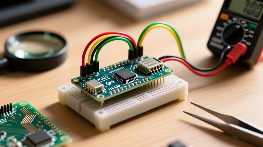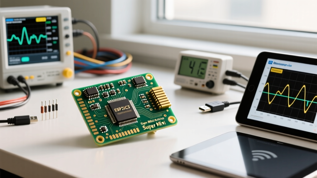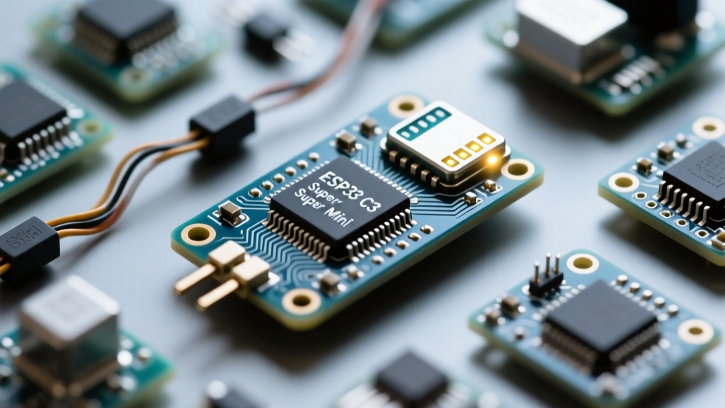

The ESP32-C3 Super Mini has rapidly become a darling of the IoT and DIY electronics community. Offering a RISC-V architecture, Wi-Fi and Bluetooth 5 LE capabilities, and a footprint barely larger than a postage stamp, it is a marvel of modern microcontroller design. However, as developers rush to integrate this ultra-compact board into their projects, they frequently encounter a frustrating hardware ambiguity: the esp32 c3 super mini built in led pin is notoriously inconsistent across different manufacturing batches.
Unlike official development boards that adhere to strict silkscreen standards, the 'Super Mini' designation is largely a market-driven term adopted by various Shenzhen-based manufacturers. This ecosystem fragmentation means that the onboard status LED—a critical tool for debugging, heartbeat monitoring, and boot verification—can be wired to several different GPIO pins depending on the exact factory run. In this comprehensive ecosystem overview, we will dissect the hardware variations, uncover dangerous strapping pin conflicts, and provide actionable firmware solutions for your ESP32-C3 projects.
The ESP32-C3 Super Mini Ecosystem: A Blessing and a Curse
To understand why the built-in LED pin varies, we must first look at the broader ESP32-C3 ecosystem. Espressif Systems released the ESP32-C3 as a cost-effective, drop-in replacement for the aging ESP8266. The official ESP32-C3 Datasheet outlines the chip's capabilities, but it does not dictate a single, rigid form factor for third-party development boards.
The 'Super Mini' boards flooded the market as ultra-cheap, generic alternatives to premium offerings like the Seeed XIAO or the Waveshare ESP32-C3-Zero. Because these generic boards prioritize minimizing the PCB footprint over user-friendly documentation, silkscreen labels for the onboard LED are often omitted entirely. Furthermore, as factories swap out component suppliers to maintain the sub-$2 price point, the physical LED and its corresponding GPIO routing can change without any revision to the board's schematic.
Community Consensus: Never assume the pinout of a generic ESP32-C3 Super Mini based on a single forum post. Always verify the LED routing with a multimeter's continuity test before deploying battery-powered firmware that relies on deep sleep wake-up indicators.
Pinpointing the ESP32 C3 Super Mini Built In LED Pin
When dealing with the esp32 c3 super mini built in led pin, you will generally encounter three distinct hardware configurations. Identifying which variant you hold in your hand is the first step toward successful firmware deployment.
Variant A: The WS2812 RGB LED on GPIO 8
Influenced heavily by the popular Waveshare ESP32-C3-Zero Wiki and schematics, many high-quality Super Mini clones utilize an addressable WS2812B RGB LED. In this configuration, the data line is almost universally routed to GPIO 8. This allows developers to create complex, multi-color status indicators using libraries like FastLED or the ESP-IDF RMT peripheral.
Variant B: The Standard SMD LED on GPIO 21
Some manufacturing batches eschew the RGB LED to cut costs, opting instead for a standard blue or green SMD LED paired with a current-limiting resistor. On many of these generic boards, this simple LED is tied to GPIO 21. This is generally considered the 'safest' pin for a standard LED, as GPIO 21 does not interfere with the chip's boot strapping process.
Variant C: The Problematic GPIO 2 Routing
The most troublesome variant—and unfortunately, a common one in the cheapest bulk packs—routes the standard LED to GPIO 2. While GPIO 2 is the traditional 'built-in LED' pin for the original ESP8266 and standard ESP32 DevKits, using it on the ESP32-C3 introduces severe hardware conflicts that we will explore in the next section.
The Strapping Pin Trap: Why Your LED Causes Boot Loops
The most critical piece of E-E-A-T knowledge regarding the ESP32-C3 architecture is understanding its strapping pins. Strapping pins are sampled by the internal bootloader during a hard reset to determine the chip's boot mode and log output behavior. According to Espressif's official hardware guidelines, the ESP32-C3 has three primary strapping pins: GPIO 2, GPIO 8, and GPIO 9.
If your Super Mini board features a standard LED wired to GPIO 8 (rather than a high-impedance WS2812), you are walking into a hardware trap. If the LED circuit includes a pull-down resistor to ground, it will force GPIO 8 low during boot. This specific state alters the boot mode and can suppress the U0TXD boot log, leaving you completely blind when debugging via the serial monitor.
Similarly, if the LED is on GPIO 2 with a pull-down resistor, it forces the chip into SPI boot mode rather than the standard download mode, occasionally causing the board to reject firmware uploads from the Arduino IDE or ESP-IDF. If you suspect your board is stuck in a boot loop or failing to enter flash mode, desoldering the LED's current-limiting resistor is a common, albeit extreme, hardware workaround favored by advanced makers.
Firmware Configuration: Driving the LED Across Ecosystems
Once you have physically identified your board's LED pin, you must map it correctly in your firmware. The Arduino-ESP32 GitHub Repository core definitions do not always account for generic clone boards, meaning the default LED_BUILTIN macro may point to the wrong GPIO.
Standard Digital Write (GPIO 2 or 21)
For standard SMD LEDs, you must manually define the pin at the top of your sketch. Note that on some cheap clones, the LED is wired in an 'active-low' configuration, meaning you must write LOW to turn it on.
// Define the specific pin for your Super Mini variant
#define SUPER_MINI_LED 21

void setup() {
  pinMode(SUPER_MINI_LED, OUTPUT);
}

void loop() {
  digitalWrite(SUPER_MINI_LED, HIGH); // Turn OFF (if active-low)
  delay(500);
  digitalWrite(SUPER_MINI_LED, LOW);  // Turn ON
  delay(500);
}
Addressable RGB Control (GPIO 8)
If your board features the WS2812 on GPIO 8, you cannot use standard digital writes. You must utilize the Neopixel or FastLED libraries, ensuring the data rate matches the WS2812B specification (typically 800kHz).
Ecosystem Alternatives: When the Super Mini Isn't Enough
While the ESP32-C3 Super Mini is incredibly cheap, the lack of standardized documentation and the risk of strapping pin conflicts drive many professional developers toward alternative ecosystem boards. Below is a comparison of the C3 landscape to help you decide if the Super Mini's LED quirks are worth the cost savings.
| Board Model | LED Pin | LED Type | USB-UART Chip | Ecosystem Reliability |
|---|---|---|---|---|
| Generic Super Mini | GPIO 8 / 21 / 2 | SMD or WS2812 | Native USB / CH340 | Low (High variance) |
| Waveshare C3-Zero | GPIO 8 | WS2812 RGB | Native USB | High (Documented) |
| Seeed XIAO ESP32-C3 | None (User LED absent) | N/A | Native USB | Very High (Premium) |
| Espressif DevKitM-1 | GPIO 8 | WS2812 RGB | CP2102 | Maximum (Official) |
Troubleshooting the 'Dead LED' Syndrome
If you have uploaded a blink sketch and the esp32 c3 super mini built in led pin remains dark, follow this systematic troubleshooting framework before discarding the board:
- Verify Active-Low Logic: Many generic boards wire the LED cathode to the GPIO and the anode to 3.3V. Invert your
digitalWritelogic to test this. - Check the WS2812 Power State: If your board has an RGB LED, it will not illuminate with standard digital writes. You must send a data packet via a Neopixel library to 'wake up' the internal driver chip.
- Inspect for Cold Solder Joints: The Super Mini's PCB is densely packed. Use a magnifying loupe to check the resistor adjacent to the LED. Reflowing a cold solder joint with a fine-tip iron resolves about 20% of 'dead LED' returns.
- Measure GPIO Voltage: Use a multimeter to probe the suspected LED pin during a
HIGHstate. If you see 3.3V but no light, the LED diode itself is likely blown—a common casualty if the user accidentally backfed 5V into the 3.3V rail via a breadboard wiring error.
Final Thoughts on the C3 Ecosystem
The ESP32-C3 Super Mini represents the wild west of modern microcontroller ecosystems. It offers unparalleled value and a brilliantly compact footprint, but it demands a higher level of hardware literacy from the user. By understanding the nuances of the esp32 c3 super mini built in led pin, recognizing the dangers of strapping pin interference, and systematically verifying your specific board's variant, you can harness the full power of this RISC-V powerhouse without falling victim to its silicon quirks. Always test your hardware, trust your multimeter, and adapt your firmware to the board you actually have, not the one the documentation claims you bought.