
The RISC-V Maker Standard: Understanding the C3 Mini Form Factor
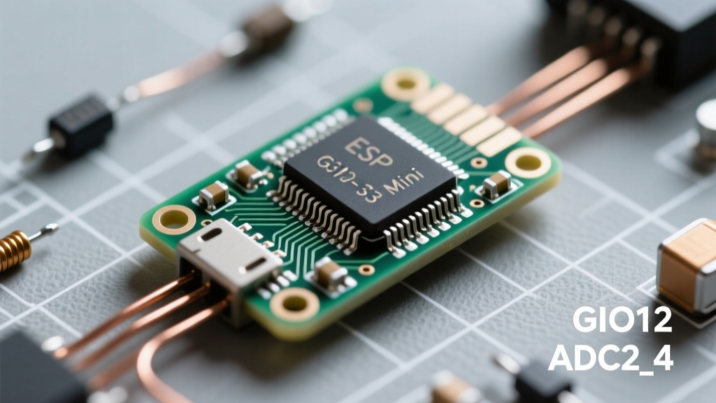
When the community transitioned from the classic ESP8266 and dual-core ESP32 to the single-core RISC-V architecture, the ESP32-C3 emerged as the undisputed king of low-cost IoT. The "Mini" or "SuperMini" development boards—often produced by WeAct, Lolin, or generic fabrication houses—shrink the ESP32-C3FH4 chip into a footprint rivaling the Arduino Nano. However, the ESP32-C3 Mini pinout is notorious for tripping up migrating makers. Unlike the original ESP32, the C3 lacks capacitive touch, features a different ADC topology, and relies heavily on multiplexed strapping pins. This community-sourced guide cuts through the datasheet noise to provide real-world wiring frameworks, verified voltage tolerances, and hardware quirks you need to know before soldering your next prototype.
Community-Verified ESP32-C3 Mini Pinout Map
The standard C3 Mini board typically breaks out 15 to 20 usable GPIOs. Below is the community-verified mapping, noting default states and hidden hardware multiplexing that frequently causes boot failures.
| Board Pin | GPIO Number | Primary Function | Community Notes & Warnings |
|---|---|---|---|
| 5V | N/A | Power Input | USB 5V or external regulated 5V. Feeds onboard LDO. |
| GND | N/A | Ground | Common ground. Use multiple pins for high-current SPI/I2C bus returns. |
| 3V3 | N/A | Power Output | Onboard LDO output. Max safe draw is ~300mA after board overhead. |
| D0 | GPIO0 | ADC1_CH0 / I2S | Boot strapping pin. Must be HIGH for normal SPI flash boot. |
| D1 | GPIO1 | ADC1_CH1 / I2S | Standard GPIO. Safe for PWM and I2C SDA. |
| D2 | GPIO2 | ADC1_CH2 / I2S | Strapping pin for log printing. Avoid external pull-downs during boot. |
| D3 | GPIO3 | ADC1_CH3 / I2S | Standard GPIO. Excellent for SPI MOSI. |
| D4 | GPIO4 | ADC1_CH4 / I2S | Standard GPIO. Excellent for SPI MISO. |
| D5 | GPIO5 | ADC2_CH0 | ADC2 is disabled when WiFi is active. Use ADC1 instead. |
| D6 | GPIO6 | I2C SCL / SPI | Default I2C Clock pin in Arduino Core. |
| D7 | GPIO7 | I2C SDA / SPI | Default I2C Data pin in Arduino Core. |
| D8 | GPIO8 | WS2812 / SPI | Crucial strapping pin. Controls boot mode. Has onboard LED on many Minis. |
| D9 | GPIO9 | Boot Button | Strapping pin for JTAG vs USB boot. Pulled HIGH by default. |
| D10 | GPIO10 | SPI CS | Default Chip Select for external SPI peripherals. |
| D18 | GPIO18 | USB D- | Native USB-CDC. Do not use for standard GPIO if using Serial over USB. |
| D19 | GPIO19 | USB D+ | Native USB-CDC. Do not use for standard GPIO if using Serial over USB. |
| D20 | GPIO20 | UART RX | Hardware UART0 RX. Connected to USB-UART bridge on some board variants. |
| D21 | GPIO21 | UART TX | Hardware UART0 TX. Connected to USB-UART bridge on some board variants. |
Strapping Pins: The #1 Cause of C3 Boot Failures
If your ESP32-C3 Mini refuses to execute your sketch and hangs in a boot loop, strapping pins are almost always the culprit. The C3 architecture samples specific GPIOs during the reset phase to determine the boot mode. According to the official Espressif ESP32-C3 Datasheet, mismanaging these pins in your circuit design will brick the boot sequence.
GPIO8: The Boot Mode Selector
GPIO8 dictates whether the chip boots from SPI Flash or the USB/JTAG interface. On most Mini boards, there is an internal weak pull-up. If you connect a sensor or relay that pulls GPIO8 LOW during power-on, the chip will enter the ROM bootloader and fail to run your application. Community Fix: Never use GPIO8 for active-low switches or sensors that initialize immediately on power-up.
GPIO2 and GPIO9: Logging and JTAG
GPIO2 controls whether the ROM bootloader prints initialization logs to the UART. GPIO9 determines if the USB interface acts as a CDC device or a JTAG debugger. The ESP-IDF GPIO Documentation explicitly warns against adding external pull-down resistors to GPIO9 if you intend to use the native USB-CDC features for serial monitoring.
ADC Realities: 12-Bit SAR and the Non-Linearity Problem
Makers migrating from the original ESP32 often assume the ADC behavior is identical. The ESP32-C3 features a 12-bit SAR ADC (up to 4096 raw values), but community bench testing has revealed significant non-linearity, particularly near the 3.3V rail.
- Channels: ADC1 supports GPIO0 through GPIO4. ADC2 supports GPIO5.
- WiFi Conflict: Just like the original ESP32, ADC2 is completely disabled when the WiFi radio is active. Always design analog sensor circuits on ADC1 (GPIO0-4).
- The 2.5V Wall: Community oscilloscope and multimeter logs show that the C3 ADC becomes highly non-linear above 2.5V. If you are reading a 0-3.3V analog signal, expect a compression of values between 2.5V and 3.3V. Pro-Tip: Use a simple voltage divider to scale your 3.3V sensor outputs down to a 2.0V maximum before feeding them into the C3 Mini's ADC pins.
Power Delivery and Deep Sleep Currents
The ESP32-C3 is marketed for ultra-low-power battery applications, but the "Mini" development board adds overhead that ruins deep sleep metrics if you aren't careful.
Community Benchmark: A bare ESP32-C3FH4 chip draws roughly 5µA in deep sleep. However, a generic C3 Mini board with an onboard LDO, USB-CDC resistors, and a power LED will idle around 12mA to 18mA. To achieve true micro-amp deep sleep, you must physically desolder the power LED and bypass the onboard LDO by feeding 3.3V directly into the 3V3 pin from an external ultra-low-quiescent regulator like the TPL5110 or HT7333.
Native USB-CDC vs. UART Bridging
One of the most confusing aspects of the ESP32-C3 Mini pinout is how serial communication is handled. The C3 chip has native USB 2.0 Full-Speed support via GPIO18 and GPIO19. However, many budget "Mini" boards still include a CH340 or CP2102 UART-to-USB bridge chip connected to GPIO20 and GPIO21.
When using the Arduino Core for ESP32, you must configure your board definition correctly. If your board has a UART bridge, you use standard Serial.print(). If your board relies on native USB-CDC (often labeled as "SuperMini" or "C3 DevKitM-1"), you must enable "USB CDC On Boot" in the Arduino IDE tools menu, and use Serial.begin() only after the USB stack has initialized, otherwise your serial output will vanish into the void.
RF Performance and Antenna Keep-Out Zones
The C3 Mini typically utilizes a PCB trace antenna or a small ceramic chip antenna. Because the board is so compact, makers frequently solder pin headers and wrap copper wire around the antenna area for prototyping. This destroys the RF impedance matching. Maintain a strict 5mm keep-out zone around the antenna tip. If you are mounting the C3 Mini inside a metal enclosure or a carbon-fiber drone frame, you must select a Mini variant that features an IPEX (U.FL) connector and route an external 2.4GHz antenna to maintain a stable WiFi and Bluetooth 5 (LE) connection.
Flashing Troubleshooting: The Boot Dance
If the Arduino IDE fails to upload your sketch, throwing a "Timed out waiting for packet header" error, the board has failed to enter the ROM bootloader. Because the C3 Mini often lacks an automatic DTR/RTS auto-reset circuit found on larger NodeMCU boards, you must perform the manual boot dance:
- Press and hold the BOOT button (GPIO9) on the board.
- While holding BOOT, press and release the RESET button.
- Release the BOOT button.
- Click "Upload" in the Arduino IDE immediately.
Once the upload completes, press the RESET button one final time to boot into your newly flashed application.