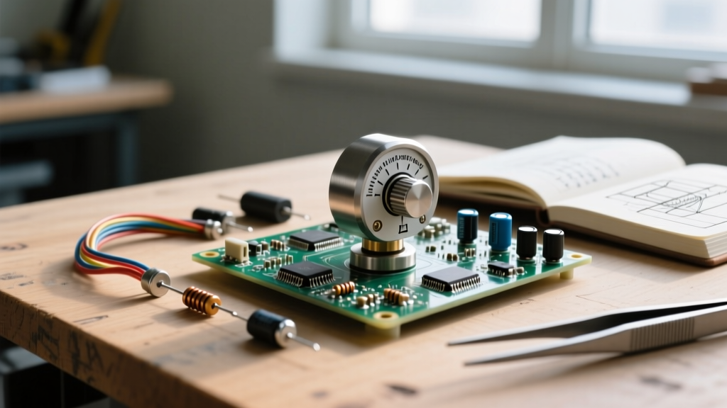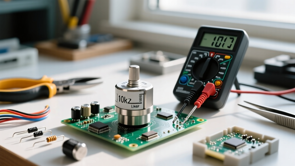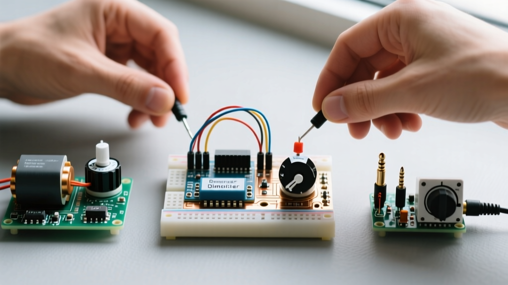

The Anatomy of a Variable Resistor
Before diving into project-based learning, we must establish the foundational physics of the component. A potentiometer is a three-terminal resistor with a sliding or rotating contact (the wiper) that forms an adjustable voltage divider. When you make a potentiometer connection, you are typically interacting with three pins: Pin 1 (Clockwise/High), Pin 2 (Wiper/Output), and Pin 3 (Counter-Clockwise/Ground).
While reading datasheets for standard components like the Bourns 3386 series cermet trimmers or Alpha RD-B10K panel mounts is useful, true understanding comes from application. A flawed potentiometer connection will introduce ADC jitter, thermal runaway, or audio hum. By building three distinct circuits, you will master the component's behavior across digital, high-current, and analog audio domains.
Project 1: Microcontroller Analog Input (The Voltage Divider)
The most common entry point for makers is reading a dial position with a microcontroller like an Arduino or ESP32. In this configuration, the potentiometer acts as a dual-resistor voltage divider.
The Wiring Topology
- Pin 1: Connected to 5V (or 3.3V VCC, depending on your MCU's logic level).
- Pin 3: Connected to GND.
- Pin 2 (Wiper): Connected to an Analog-to-Digital Converter (ADC) pin, such as A0.
As you rotate the shaft, the wiper sweeps across the resistive carbon or cermet track, outputting a voltage between 0V and VCC. The MCU reads this voltage and maps it to a digital value (e.g., 0-1023 for a 10-bit ADC).
Expert Troubleshooting: Eliminating ADC Jitter
A frequent complaint in beginner forums is 'jumpy' sensor readings. This is rarely a bad potentiometer connection; it is usually electromagnetic interference (EMI) or high-impedance ADC sampling artifacts. To fix this, solder a 100nF (0.1µF) ceramic capacitor directly between the wiper (Pin 2) and GND (Pin 3). This creates a passive low-pass RC filter, smoothing out high-frequency noise and stabilizing the analog reading without requiring complex software debouncing.
Project 2: High-Current Motor Speed Control (The Rheostat Trap)
Can you use a potentiometer to control a DC motor's speed directly? Theoretically, yes, by wiring it as a rheostat (using only Pin 1 and Pin 2). Practically, doing so with standard components is a recipe for catastrophic failure.
The Wiper Current Limitation
Consider a standard 10KΩ, 0.5W potentiometer. Using the power formula (P = I²R), the maximum continuous current through the entire track is roughly 7mA. If you rotate the wiper to the 10% mark (1KΩ), the localized max current before the carbon track vaporizes is about 22mA. A small hobby motor draws 200mA to 500mA on startup. Connecting a motor directly to the wiper will instantly burn out the resistive element, leaving you with an open circuit.
The Correct Approach: MOSFET Gate Drive
Instead of passing load current through the potentiometer, use it to control a logic-level MOSFET (like the IRLZ44N).
- Wire the potentiometer as a voltage divider (Pins 1, 2, and 3 to 12V, Gate, and GND).
- Connect the MOSFET Gate to the wiper (Pin 2).
- Wire the motor between the 12V supply and the MOSFET Drain. Connect the Source to GND.
Now, the potentiometer connection only sources a few microamps to charge the MOSFET's gate capacitance, while the MOSFET handles the heavy motor current. For further reading on power limits and derating, consult the Bourns 3386 Series Datasheet.
Project 3: Hi-Fi Audio Volume Attenuator (Logarithmic Taper)
Audio engineering requires a nuanced understanding of human hearing, which perceives loudness logarithmically, not linearly. If you use a Linear (B-taper) potentiometer for a volume knob, the audio will seem to jump from silent to deafening within the first 20% of the rotation.
Selecting the Audio Taper
For audio projects, you must source an Audio Taper (A-taper) potentiometer, such as the Alps RK09 series or a Bourns PDB181-GTR. In an A10K or A50K pot, the resistive track is curved so that 50% shaft rotation yields roughly 10% to 15% of the total resistance. This matches the logarithmic response of the human ear, providing a smooth, perceived-linear volume swell.
Star Grounding to Prevent Hum
When wiring a stereo audio mixer, the potentiometer connection grounding scheme is critical. Never daisy-chain the ground wires from the input jack, the pot casing, and the output jack. This creates a ground loop, resulting in a 50/60Hz mains hum. Instead, use star grounding: run individual ground wires from the pot casing, Pin 3, and the audio jacks to a single, centralized ground lug on the chassis.
Taper Selection Matrix
| Taper Type | Marking Code | 50% Rotation Resistance | Primary Application |
|---|---|---|---|
| Linear | B (e.g., B10K) | 50% | Sensor inputs, voltage dividers, LED dimming |
| Audio (Logarithmic) | A (e.g., A50K) | ~10% - 15% | Volume controls, audio mixers, synth filters |
| Reverse Audio | C (e.g., C10K) | ~85% - 90% | Specialized cross-faders, reverse-sweep effects |
For a deeper dive into the mathematics of audio tapers and why standard 'A' tapers often fall short of true logarithmic curves, Rod Elliott's Potentiometer Tutorial on Sound.au is an industry-standard reference.
Expert Soldering and Failure Modes
Even with the correct circuit topology, poor physical soldering can ruin a potentiometer. The internal phenolic resin and carbon tracks are highly sensitive to thermal shock.
Pro-Tip: When making a potentiometer connection, tin your wires first. Apply flux to the lug, and keep the soldering iron on the terminal for no longer than 3 seconds. Prolonged heat will melt the internal plastic stopper or warp the carbon track, causing permanent 'scratchy' dead spots when rotating the shaft.
Another common failure mode is mechanical stress. If you use the potentiometer as a structural mount for a heavy PCB, the internal wiper tension spring can deform. Always use the mounting nut and washer on the panel face to bear mechanical loads, keeping the soldered lugs strictly for electrical continuity.
By progressing from simple voltage dividers to MOSFET gate drives and finally to star-grounded audio circuits, you transition from merely following tutorials to engineering robust, noise-free hardware. Mastering the potentiometer connection is ultimately about understanding the boundary between signal control and power delivery.
For foundational theory on variable resistors and rheostat wiring, Electronics Tutorials offers excellent schematic breakdowns to supplement your hands-on builds.