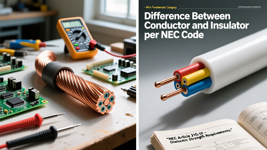

Beyond Basic Physics: The Code-Driven Definition
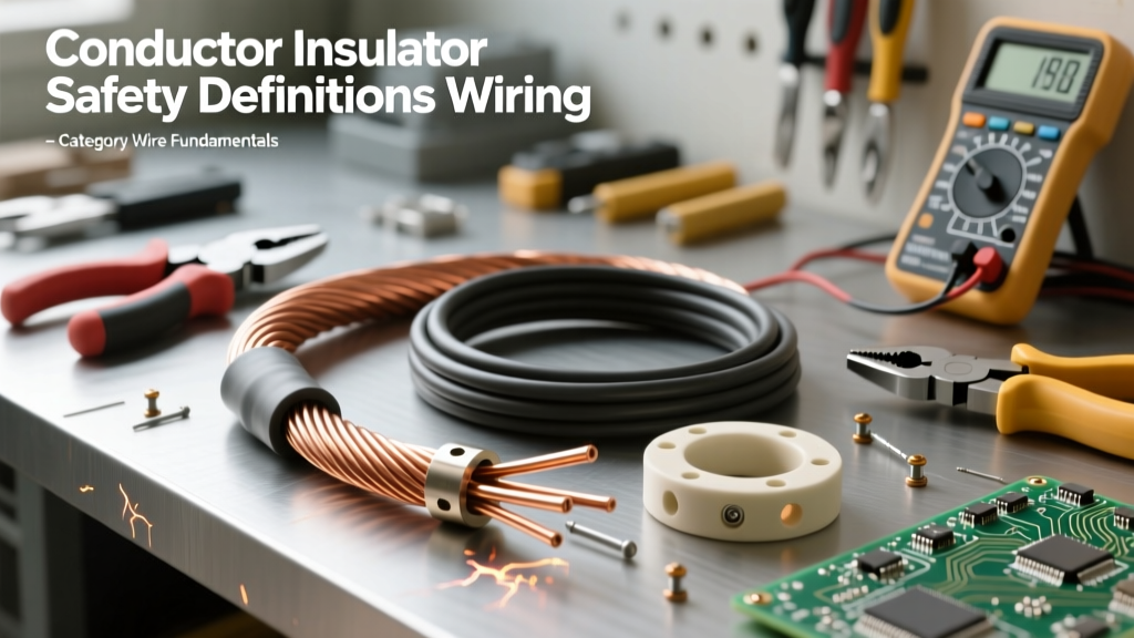
In high school physics, the difference between conductor and insulator is taught simply as a matter of electron mobility: conductors have free valence electrons that allow current to flow, while insulators have tightly bound electrons that resist it. However, for electrical contractors, engineers, and inspectors, this basic atomic theory is insufficient. In the field, the difference is defined by strict code parameters, thermal limits, and dielectric integrity.
The NFPA 70 National Electrical Code (NEC) does not evaluate materials based on bandgap theory. Instead, it evaluates conductors based on ampacity (the maximum continuous current they can carry without exceeding their temperature rating) and insulators based on dielectric strength and thermal endurance. Understanding this code-driven distinction is critical for preventing thermal runaway, insulation breakdown, and catastrophic arc faults.
Conductors in the NEC: Ampacity and Material Mandates
From a code perspective, a conductor's primary job is to transport electrical energy with minimal resistive heating (I²R losses). The NEC strictly regulates the materials, sizing, and stranding of conductors to ensure they perform this function safely under continuous load.
Copper vs. Aluminum: Article 310 Compliance
NEC Article 310 governs conductors for general wiring. The code recognizes two primary metallic conductors, but with strict caveats:
- Copper: The gold standard for conductivity. The NEC assumes annealed copper with 100% IACS (International Annealed Copper Standard) conductivity when referencing standard ampacity tables.
- Aluminum: Historically prone to thermal expansion and oxidation issues at terminations, modern code requires aluminum conductors to be manufactured from AA-8000 series alloy (per NEC 310.14). This specific alloy provides the necessary creep resistance and tensile strength to prevent loose connections, which are a primary cause of residential fires.
Insulators and Dielectrics: Voltage and Thermal Boundaries
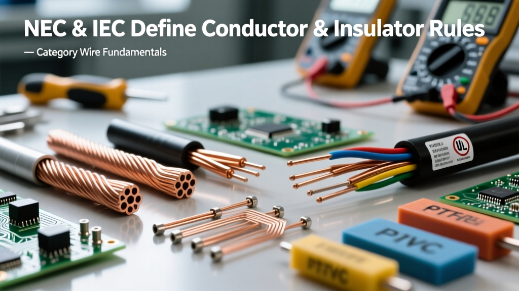
If the conductor is the highway for electrons, the insulator is the guardrail. The insulator's function is to maintain dielectric integrity—preventing current from leaking to ground, adjacent phases, or personnel. The UL 83 Standard for Thermoplastic-Insulated Wires and Cables and the NEMA wire and cable standards dictate rigorous testing for these materials.
Decoding Wire Insulation Ratings (THHN, XHHW-2, USE-2)
The letters printed on a wire's jacket define the insulator's chemical makeup and environmental limits. Misinterpreting these letters is a common code violation.
- THHN / THWN-2: Thermoplastic (PVC) insulation with a nylon outer jacket. Rated for 90°C in dry locations and 75°C in wet locations. The nylon jacket provides exceptional resistance to oil, gasoline, and mechanical abrasion, but it can be prone to 'skinning' if pulled through conduit with excessive friction.
- XHHW-2: Cross-linked Polyethylene (XLPE). This is a thermoset insulator, meaning it undergoes a chemical change during manufacturing that makes it highly resistant to heat and moisture. It lacks the slippery nylon jacket of THHN but offers superior dielectric strength and a thinner insulation wall, allowing for more conductors in a single conduit.
- USE-2: Underground Service Entrance. Rated specifically for direct burial, featuring an insulator highly resistant to soil chemicals, moisture, and UV degradation.
Expert Note: While THHN is rated for 90°C, NEC 110.14(C) generally restricts the ampacity of circuits under 100A to the 60°C column of Table 310.16 due to the temperature limitations of standard residential breakers and receptacles. The 90°C rating is primarily used for derating purposes when bundling multiple conductors in a single raceway.
The Boundary Layer: Failure Modes and the Montsinger Rule
The most critical difference between conductor and insulator lies in how they fail. A conductor fails by melting or fusing (acting as an unintentional fuse), while an insulator fails by breaking down, leading to short circuits, ground faults, and arc flashes.
Thermal Degradation and the Montsinger Rule
Insulation failure is rarely instantaneous; it is usually a cumulative thermal degradation process. Electrical engineers rely on Montsinger's Rule (often called the 10-Degree Rule), which states that for every 10°C an insulator operates above its rated temperature, its useful lifespan is cut in half. For example, a THHN wire rated for 90°C that is forced to operate continuously at 100°C due to improper conduit fill or harmonic heating will lose 50% of its dielectric life expectancy.
Dielectric Breakdown and Partial Discharge
When voltage exceeds the dielectric strength of the insulator (measured in Volts per mil), the molecular bonds of the plastic or rubber shatter. In medium and high-voltage applications, this begins as partial discharge—microscopic sparking inside voids within the insulation. Over time, this creates electrical 'trees' (Lichtenberg figures) that eventually bridge the gap between the conductor and the ground, resulting in a catastrophic fault.
Comparison Matrix: Conductor vs. Insulator Properties
| Property | Conductor (e.g., Copper / AA-8000 Al) | Insulator (e.g., XLPE / PVC) |
|---|---|---|
| Primary NEC Metric | Ampacity (Circular Mils, AWG/kcmil) | Temperature Rating (°C) & Voltage Rating (e.g., 600V) |
| Key Material Trait | Low Electrical Resistivity | High Dielectric Strength (V/mil) |
| Primary Failure Mode | Thermal Melting / Annealing (Loss of tensile strength) | Dielectric Breakdown / Carbon Tracking / Thermal Embrittlement |
| Governing NEC Article | Article 310 (Conductors for General Wiring) | Article 300 (Wiring Methods) & UL Product Standards |
| Environmental Threat | Oxidation, Galvanic Corrosion, Creep | UV Radiation, Moisture, Ozone, Solvents |
The Grounding Paradox: Bare Conductors and Insulated Shields
The NEC introduces a fascinating paradox regarding the Equipment Grounding Conductor (EGC). A bare copper ground wire is technically a conductor that is completely devoid of an insulator.
How does this not violate the fundamental safety requirement of separating current-carrying parts from grounded surfaces? The answer lies in the system design. The bare EGC relies entirely on the dielectric integrity of the adjacent insulated conductors (the hot and neutral wires) to prevent a fault. If the insulation on the hot wire fails, the bare conductor provides a low-impedance path back to the source, triggering the breaker. Sizing this bare conductor is strictly governed by NEC Table 250.122, ensuring it can handle the maximum available fault current without vaporizing before the overcurrent protection device clears the circuit.
Summary Checklist for Code Compliance
When designing or troubleshooting a circuit, keep these code-driven distinctions in mind:
- Verify Conductor Alloy: Ensure aluminum terminations are rated for CO/ALR and use AA-8000 series wire with antioxidant compound.
- Respect Insulation Wet/Dry Ratings: Never use THHN in a wet location (like an underground conduit) unless it is explicitly dual-rated as THWN-2.
- Calculate Conduit Fill: Overcrowding a conduit traps heat, accelerating insulator degradation via the Montsinger Rule, even if the conductor itself hasn't reached its melting point.
- Match Lug Ratings: The insulator may be rated for 90°C, but if the breaker lug is only rated for 75°C, your legal ampacity is capped at the 75°C limit.