
The Anatomy of an NEC Wire Sizes Table
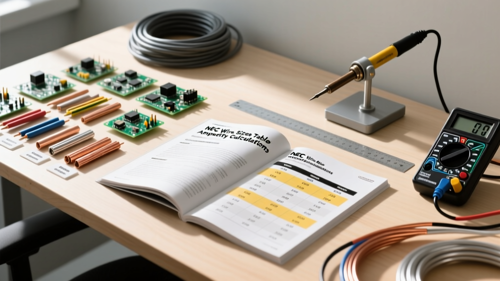
When electrical professionals and advanced DIYers reference a wire sizes table, they are typically looking at Table 310.15(B)(16) of the National Electrical Code (NEC). However, treating this table as a simple lookup chart is a critical mistake that leads to overheated conductors, tripped breakers, and potential fire hazards. To properly size a wire, you must understand the intersection of base ampacity, terminal temperature limits, ambient temperature correction, and conductor bundling adjustments.
A standard wire sizes table is divided into distinct temperature columns: 60°C, 75°C, and 90°C. These columns do not represent the temperature of the wire itself, but rather the thermal rating of the insulation material. Common building wires like THHN and THWN-2 are rated for 90°C, while older or specialized insulations like TW are limited to 60°C. The ampacity values listed are based on an ambient air temperature of 30°C (86°F). If your installation environment is hotter, or if you are grouping multiple wires together, the base numbers in the table must be mathematically reduced.
AWG vs. kcmil: Where the Shift Happens
The table transitions from American Wire Gauge (AWG) to thousands of circular mils (kcmil) at 4/0 AWG. While AWG uses a logarithmic scale where a smaller number indicates a thicker wire (e.g., 10 AWG is thicker than 14 AWG), kcmil uses a linear scale based on the cross-sectional area of the conductor. A 250 kcmil wire has exactly 250,000 circular mils of conductive area. This distinction is vital when calculating voltage drop over long distances, as circular mils are a direct variable in the resistance formula.
Comprehensive Wire Sizes Table (Copper & Aluminum)
Below is a condensed reference chart based on Cerro Wire Ampacity Charts and NEC guidelines for standard copper and aluminum conductors. Always verify with the latest NEC edition for your specific jurisdiction.
| Wire Size (AWG/kcmil) | 60°C Copper (Amps) | 75°C Copper (Amps) | 90°C Copper (Amps) | 75°C Aluminum (Amps) | 90°C Aluminum (Amps) |
|---|---|---|---|---|---|
| 14 AWG | 15 | 20 | 25 | - | - |
| 12 AWG | 20 | 25 | 30 | - | - |
| 10 AWG | 30 | 35 | 40 | - | - |
| 8 AWG | 40 | 50 | 55 | 30 | 45 |
| 6 AWG | 55 | 65 | 75 | 40 | 55 |
| 4 AWG | 70 | 85 | 95 | 55 | 75 |
| 2 AWG | 95 | 115 | 130 | 75 | 100 |
| 1/0 AWG | 125 | 150 | 170 | 100 | 135 |
| 4/0 AWG | 230 | 260 | 310 | 180 | 250 |
The Terminal Temperature Rule (NEC 110.14(C))
Before performing any derating calculations, you must understand the terminal temperature limitation rule outlined in NEC 110.14(C). Even if you install 90°C THHN wire, the breaker lugs and receptacle terminals are typically rated for only 75°C. Therefore, the base ampacity used to select your overcurrent protective device (OCPD) must be pulled from the 75°C column (or 60°C for circuits under 100A using older equipment). The 90°C column is strictly reserved as a starting point for applying ambient temperature and bundling correction factors.
Step-by-Step Calculation Tutorial: Sizing a 60A Circuit
Let us apply a real-world scenario to demonstrate how to properly use a wire sizes table for a complex installation. Imagine you are wiring a 40A continuous load (like a Level 2 EV charger) in an attic where the ambient temperature reaches 113°F (45°C). You are pulling four current-carrying conductors through a single conduit using Copper THHN/THWN-2 wire. The breaker terminals are rated 75°C.
Step 1: Determine Minimum Circuit Ampacity (MCA)
NEC Article 210 requires continuous loads (operating for 3 hours or more) to be multiplied by 125%.
Calculation: 40A × 1.25 = 50A MCA.
You will need a 50A breaker. Looking at the 75°C Copper column in our wire sizes table, #8 AWG is rated for exactly 50A, satisfying the terminal limitation rule.
Step 2: Apply Temperature Correction Factors
Because the attic is 45°C (113°F), we must derate the wire's capacity. According to the NEC temperature correction table for 90°C insulation, the correction factor at 45°C is 0.87.
Step 3: Adjust for Conductor Bundling
Pulling four current-carrying conductors in one raceway triggers the bundling adjustment factors in NEC Table 310.15(C)(1). For 4 to 6 conductors, the adjustment factor is 0.80 (80%).
Step 4: Calculate the Final Required Table Ampacity
We combine the derating factors to find the minimum required ampacity from the 90°C column before corrections are applied.
Formula: Required Table Ampacity = MCA / (Temp Factor × Bundling Factor)
Calculation: 50A / (0.87 × 0.80) = 50A / 0.696 = 71.8A.
Step 5: Select the Final Wire Size
Return to the 90°C Copper column in the wire sizes table. #8 AWG is only 55A (too small). #6 AWG is rated for 75A, which exceeds our 71.8A requirement. Therefore, you must install #6 AWG Copper THHN/THWN-2, protected by a 50A breaker.
Pro-Tip from the Field: Always document your derating calculations on the electrical permit or inside the panel directory. Inspectors frequently check wire sizes tables against the physical environment, and having the math readily available prevents failed inspections and costly rewiring.
Real-World Troubleshooting: Voltage Drop vs. Ampacity
A common point of confusion among DIYers is assuming that an ampacity table accounts for voltage drop. It does not. The NEC wire sizes table only ensures the wire will not melt or degrade its insulation under thermal stress. Voltage drop is a separate calculation based on the length of the run and the specific resistance of the metal.
For long runs, such as feeding a detached garage or a well pump, you must calculate voltage drop using the Circular Mil (CM) formula:
CM = (2 × K × I × D) / VD
- K = Direct Current constant (12.9 for Copper, 21.2 for Aluminum)
- I = Current in Amps
- D = One-way distance in feet
- VD = Allowable Voltage Drop (e.g., 7.2V for a 240V circuit at 3%)
If your CM calculation results in a required wire size larger than what the ampacity table dictates, you must upsize the wire to mitigate voltage drop, even if the breaker size remains the same. Tools like the Southwire Voltage Drop Calculator can automate this math, but understanding the underlying physics is what separates a master electrician from an amateur.
Common Mistakes When Reading Wire Tables
- Ignoring the Neutral as a Current-Carrying Conductor: In multi-wire branch circuits (MWBC) or 3-phase wye systems with non-linear loads (like LED lighting or computers), the neutral carries harmonic currents and must be counted in your bundling derating calculations.
- Confusing Aluminum and Copper Ratings: Aluminum expands and contracts more than copper, leading to loose connections and arcing if not terminated with antioxidant paste and proper torque. Never use the copper column if you are installing SER or USE-2 aluminum feeder cable.
- Overlooking the 240.4(B) Next-Size-Up Rule: If your calculated derated ampacity is 48A, you cannot use a 48A breaker (they do not exist). NEC 240.4(B) allows you to round up to the next standard OCPD size (50A), provided the wire's derated ampacity is still sufficient for the actual load.
Mastering the wire sizes table requires shifting your mindset from simple memorization to dynamic engineering. By systematically applying the rules of NFPA 70: National Electrical Code, you ensure that every circuit you build is not only code-compliant but optimized for safety, efficiency, and longevity.