
The Core Definition: What Does DC Stand for in Electricity?
When students, DIYers, and apprentice electricians first ask, 'what does DC stand for in electricity?', the fundamental answer is Direct Current. Unlike Alternating Current (AC), where the flow of electric charge periodically reverses direction, Direct Current flows unidirectionally. Electrons move steadily from the negative terminal to the positive terminal through a conductor, while conventional current is modeled as flowing from positive to negative.
Historically, following the 'War of the Currents' in the late 19th century, AC became the undisputed standard for power generation and grid distribution due to its ability to be easily stepped up and down in voltage via transformers. However, the modern electrical landscape has shifted dramatically. Today, DC is the native language of solar photovoltaics (PV), battery energy storage systems (BESS), electric vehicles (EVs), and Power over Ethernet (PoE) telecommunications. Consequently, understanding DC is no longer just a physics exercise; it is a critical requirement for navigating modern electrical codes and safety standards.
Direct Current in the National Electrical Code (NEC)
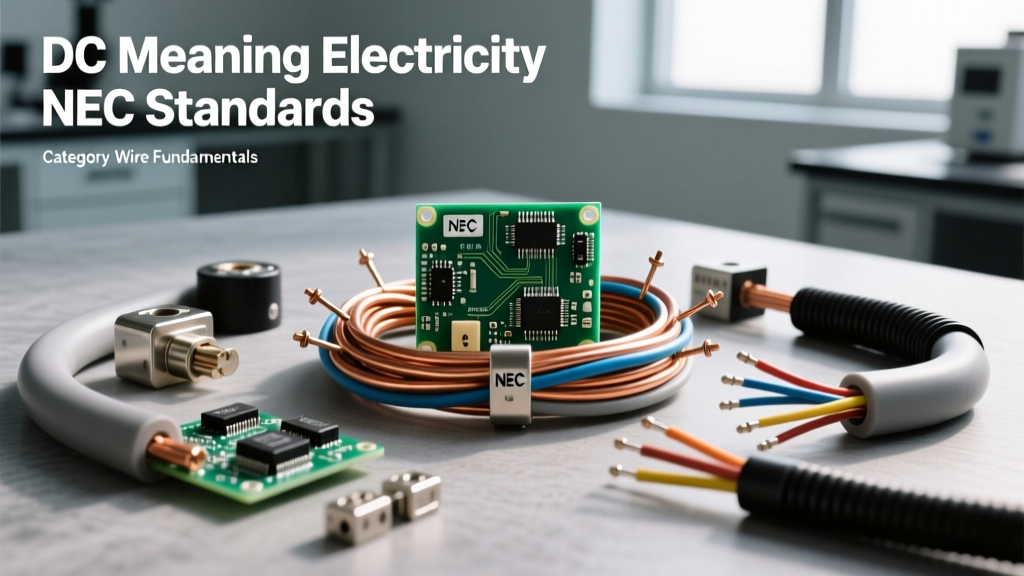
For decades, the National Fire Protection Association (NFPA) 70, widely known as the National Electrical Code (NEC), was heavily biased toward AC systems. As renewable energy and DC-based technologies have proliferated, the NEC has adapted, introducing rigorous, DC-specific articles to govern installation, wire sizing, and overcurrent protection.
Key NEC Articles Governing DC Systems
- Article 690 (Solar Photovoltaic Systems): This article dictates the installation of PV systems. Because solar panels inherently produce DC power, Article 690 provides exhaustive rules for DC source circuits, DC output circuits, and the specific labeling required to distinguish DC conductors from AC conductors in the same enclosure.
- Article 712 (Energy Storage Systems): Covering battery banks and modern lithium-ion BESS, Article 712 addresses the unique hazards of high-current DC environments, including thermal runaway prevention, specific DC disconnect requirements, and ventilation standards for off-gassing batteries.
- Article 625 (Electric Vehicle Charging System Equipment): With the rise of Level 3 DC Fast Chargers (which can operate at 400V to 800V DC and push over 300 amps), Article 625 outlines the heavy-gauge wire sizing and specialized cooling requirements necessary for DC EV supply equipment.
- Article 800 (Communications Circuits): Often overlooked, modern telecom and PoE (Power over Ethernet) rely on DC. Article 800 and related Article 725 (Class 1, 2, and 3 Remote-Control and Signaling Circuits) govern the low-voltage DC wiring that powers everything from security cameras to VoIP phones.
DC Wire Sizing: Physics, Voltage Drop, and the Skin Effect
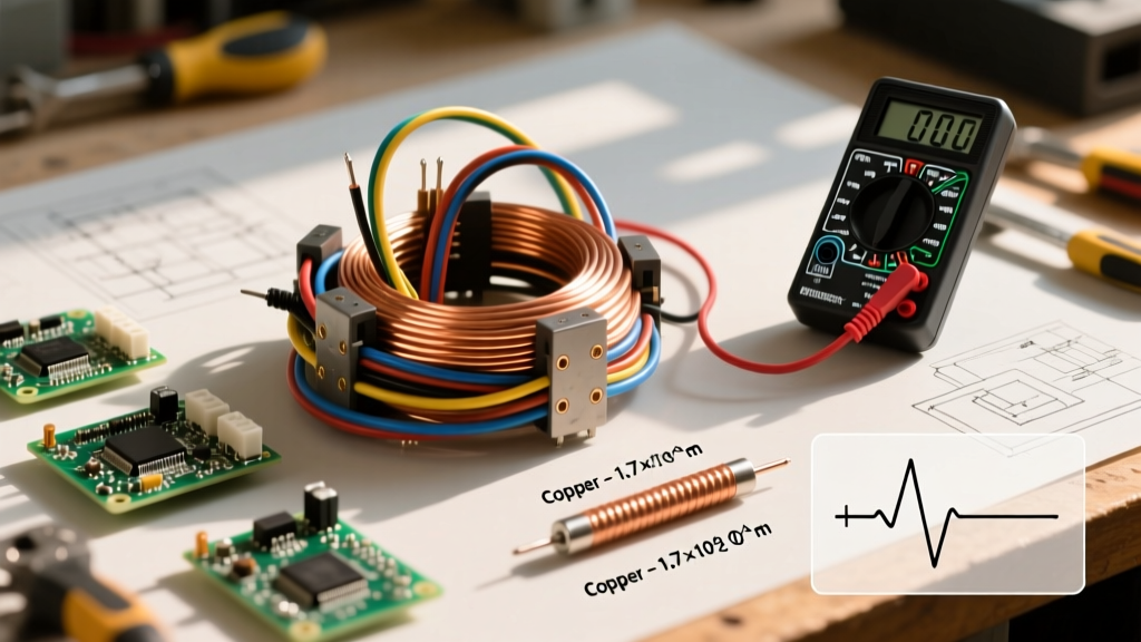
Wire sizing for DC circuits requires a different analytical approach than AC circuits, primarily due to voltage drop constraints and the absence of the 'skin effect'. In low-voltage DC systems (such as 12V, 24V, or 48V off-grid solar or marine setups), current (Amperage) is significantly higher for a given wattage compared to 120V or 240V AC systems. Using Ohm's Law and the Power Equation ($P = V imes I$), a 1,200W inverter load on a 12V DC battery bank draws 100 Amps. That same 1,200W load on a 120V AC circuit draws only 10 Amps.
Because of this massive current draw, DC wire sizing is often dictated by voltage drop limits rather than just the ampacity tables found in NEC Table 310.16. The NEC recommends a maximum of 3% voltage drop for branch circuits to ensure equipment operates efficiently. In a 12V system, a 3% drop is a mere 0.36 Volts. To prevent this voltage loss over distance, installers must use substantially larger wire gauges (often 2/0 AWG or 3/0 AWG copper) compared to standard residential AC wiring.
The Absence of the Skin Effect
In high-frequency AC circuits, the 'skin effect' forces the majority of the electron flow to travel along the outer perimeter (the 'skin') of the conductor, effectively reducing the usable cross-sectional area of the wire and increasing AC resistance. Pure DC, having a frequency of 0 Hz, does not suffer from the skin effect. The current density is distributed perfectly evenly across the entire cross-section of the wire. While this makes DC slightly more efficient per circular mil of copper, the sheer volume of current in low-voltage DC applications still necessitates massive conductors.
Standardized DC Color-Coding: NEC vs. IEC
Misidentifying a DC conductor can lead to catastrophic short circuits, equipment destruction, or fatal arc flashes. The color-coding standards for DC vary wildly depending on whether you are following US NEC standards, international IEC standards, or legacy automotive/telecom conventions. Below is a structured comparison chart to guide your installations.
| Standard / Region | Positive (Ungrounded / Hot) | Negative (Grounded / Neutral) | Equipment Ground (Earth) |
|---|---|---|---|
| US NEC (General DC & PV) | Red (or any color except white, gray, green) | White or Gray | Green, Green/Yellow, or Bare |
| IEC 60446 (Europe / Global) | Brown | Blue | Green/Yellow Stripe |
| US Telecom / PoE | Blue / White-Blue (Varies by pair) | White / Blue-White | Shield Drain Wire / Bare |
| Automotive / Marine (Legacy) | Red | Black | Chassis Ground (Bare Metal) |
Code Compliance Warning: Never mix automotive color codes (where Black is negative) with NEC residential solar installations (where Black is often used as an ungrounded AC 'hot' leg, and White is the grounded DC negative). Always label DC conductors at every termination point with voltage and polarity indicators as required by NEC 690.4.
The Arc Flash Hazard: Why DC Breakers Are Mandatory
One of the most dangerous misconceptions in electrical DIY is the belief that an AC-rated circuit breaker can be safely used on a DC circuit if the amperage rating matches. This is a severe code violation and a profound safety hazard.
When an AC circuit is interrupted by a breaker, the alternating current naturally crosses the 'zero point' 120 times per second (in a 60Hz system). This zero-crossing helps extinguish the electrical arc that forms between the separating contacts inside the breaker. DC, however, never crosses zero. When a DC circuit is broken under load, the resulting arc is continuous, incredibly hot, and can easily melt the breaker housing, ignite surrounding combustible materials, or cause a lethal arc flash.
To combat this, the NEC and UL Standards & Engagement require the use of specifically DC-rated Overcurrent Protective Devices (OCPDs) and disconnect switches. DC breakers feature specialized internal arc chutes, magnetic blowouts, and larger contact gaps designed to stretch and cool the continuous DC arc until it extinguishes. Furthermore, DC disconnects must be rated for the specific maximum system voltage (e.g., 600VDC or 1000VDC for modern solar strings), as detailed in the U.S. Department of Energy Solar PV guidelines.
Practical Troubleshooting and Code Compliance Checklist
Whether you are designing a 48V off-grid battery bank or troubleshooting a PoE network switch, adhere to this DC-specific checklist to ensure safety and code compliance:
- Verify OCPD Ratings: Check the breaker or fuse label. It must explicitly state a DC voltage rating (e.g., '125VDC' or '600VDC'). An AC-only breaker is illegal and unsafe for DC use.
- Calculate Voltage Drop First: Before selecting a wire gauge based solely on NEC ampacity tables, run the voltage drop formula: $VD = rac{2 imes K imes I imes D}{CM}$. (Where K=12.9 for copper, I=Current, D=One-way distance, CM=Circular Mils). Ensure the drop is under 3%.
- Use Proper Lugs and Torque: DC currents generate significant heat at high-resistance connections. Use oxide inhibitor paste on aluminum-to-copper transitions and always use a calibrated torque screwdriver to tighten terminal lugs to the manufacturer's exact inch-pound specifications.
- Labeling and Identification: Apply permanent, UV-resistant labels on all DC enclosures indicating the nominal battery or PV voltage, the short-circuit current rating, and the disconnect procedures.
Understanding what DC stands for in electricity is merely the starting point. True electrical mastery lies in respecting the unique physical properties of Direct Current and applying the rigorous, evolving standards of the NEC to ensure every installation is safe, efficient, and built to last.