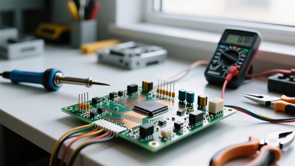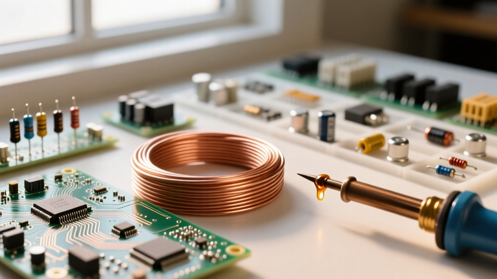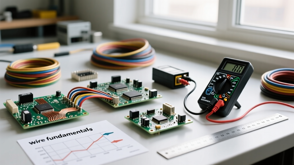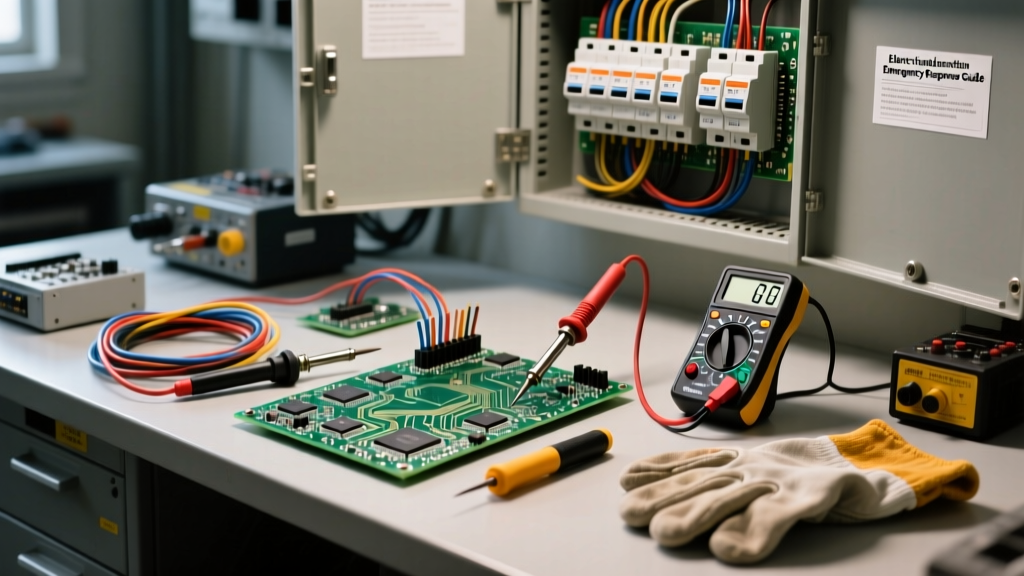

Every electrical accident—whether a minor shock or a catastrophic arc flash—traces back to a fundamental misunderstanding or failure of material boundaries. When DIYers, students, and even seasoned professionals ask, 'what are the conductors and insulators', they are usually looking for basic textbook definitions. However, from a safety and field-engineering perspective, understanding these materials goes far beyond elementary physics. It requires a deep knowledge of how these materials degrade, fail, and interact under real-world electrical, thermal, and environmental stress.
This safety guide explores the atomic reality of conductors and insulators, focusing on hidden hazards, specific failure modes, and the testing protocols required to keep electrical systems safe in residential, commercial, and industrial environments.
Defining the Boundary: What Are the Conductors and Insulators?
At the atomic level, the distinction between a conductor and an insulator lies in the behavior of valence electrons—the electrons in the outermost shell of an atom.
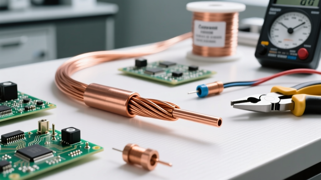
Conductors (like copper, aluminum, silver, and gold) possess one to three valence electrons that are loosely bound to their parent atoms. When a voltage (electrical pressure) is applied, these electrons easily break free and drift through the atomic lattice, creating an electrical current. From a safety standpoint, conductors are the pathways we intentionally design to carry energy, but they become lethal hazards if exposed or improperly terminated.
Insulators (like PVC, XLPE, rubber, glass, and air) have five to eight valence electrons, which are tightly bound to their nuclei. They strongly resist the flow of electrons. In electrical systems, insulators are the shields that confine the current to the conductor and protect humans and equipment from accidental contact. However, no insulator is perfect; under extreme conditions, all insulators will eventually fail.
Conductor-Specific Safety Hazards in the Field
While we often focus on the dangers of exposed conductors, the hidden hazards within terminations and material choices cause a significant percentage of electrical fires.
The Aluminum vs. Copper Thermal Expansion Hazard
Aluminum is lighter and cheaper than copper, making it popular for large feeder cables. However, aluminum's coefficient of thermal expansion is approximately 30% higher than that of copper. When an aluminum conductor is terminated in a lug designed exclusively for copper, the daily heating and cooling cycles cause the aluminum to expand and contract at a different rate. Over time, this 'creep' leads to a loose connection. A loose connection increases electrical resistance, which generates intense heat (I²R losses), eventually melting the insulation and igniting surrounding combustibles.
Safety Protocol: Always use CO/ALR (Copper/Aluminum Rated) terminals when terminating aluminum wire, and apply an antioxidant paste (like Noalox) to prevent oxidation and galvanic corrosion.
Galvanic Corrosion and Dissimilar Metals
When two dissimilar conductive metals (e.g., copper and aluminum) are in direct physical contact in the presence of an electrolyte (even ambient humidity), a galvanic cell is formed. The more reactive metal (aluminum) will rapidly corrode. This corrosion creates a high-resistance barrier that acts as an unintended heating element, leading to thermal runaway and terminal failure.
Insulator Degradation: When the Shield Fails
Insulators do not block current perfectly; they merely restrict it to microscopically small leakage currents. Understanding how insulation fails is critical for preventing ground faults and arc flashes.
Dielectric Breakdown
Every insulating material has a 'dielectric strength'—the maximum electric field it can withstand before it loses its insulating properties and allows a massive surge of current to pass through. For example, dry air has a dielectric strength of roughly 3 kV/mm, while solid PVC insulation is around 40 kV/mm. If a voltage spike (such as a lightning strike or switching surge) exceeds this threshold, the insulator is violently punctured, resulting in an arc flash or short circuit.
Thermal Aging and the Arrhenius Rule
Heat is the silent killer of insulation. According to the Arrhenius thermal aging model, for every 10°C that an insulator operates above its rated temperature, its expected lifespan is cut in half. A standard THHN wire rated for 90°C that is forced to operate at 100°C due to overloading or poor ventilation will experience rapid embrittlement. Once the insulation becomes brittle, minor vibrations can cause it to crack, exposing the live conductor.
Surface Tracking
Tracking occurs when contamination (dust, salt, or industrial chemicals) combines with moisture on the surface of an insulator. This creates a microscopically thin, highly conductive path along the exterior of the insulation. Over time, leakage current flows across this path, generating localized heat that carbonizes the insulator material. Since carbon is a conductor, this creates a permanent short-circuit path, often leading to catastrophic failure.
Material Safety and Performance Matrix
Choosing the right material for the environment is a core tenet of electrical safety. The table below outlines common materials, their thermal limits, and their primary safety vulnerabilities.
| Material | Type | Max Temp Rating | Dielectric Strength | Primary Safety Vulnerability |
|---|---|---|---|---|
| Copper (Cu) | Conductor | N/A (Melts 1085°C) | N/A | Oxidation at high temps; heavy weight causing mechanical strain. |
| Aluminum (Al) | Conductor | N/A (Melts 660°C) | N/A | Thermal creep; galvanic corrosion; requires specific torque values. |
| PVC | Insulator | 75°C - 105°C | ~40 kV/mm | Embrittlement from UV exposure; emits toxic gas when burned. |
| XLPE | Insulator | 90°C - 250°C | ~50 kV/mm | Water treeing (moisture ingress) in underground applications. |
| PTFE (Teflon) | Insulator | 250°C | ~60 kV/mm | Cold flow (deformation under sustained mechanical pressure). |
Field Verification: Testing Insulation Integrity
You cannot determine the health of an insulator simply by looking at it. Micro-cracks and internal voids are invisible to the naked eye. To ensure safety, electrical professionals rely on insulation resistance testing.
The Megohmmeter Test
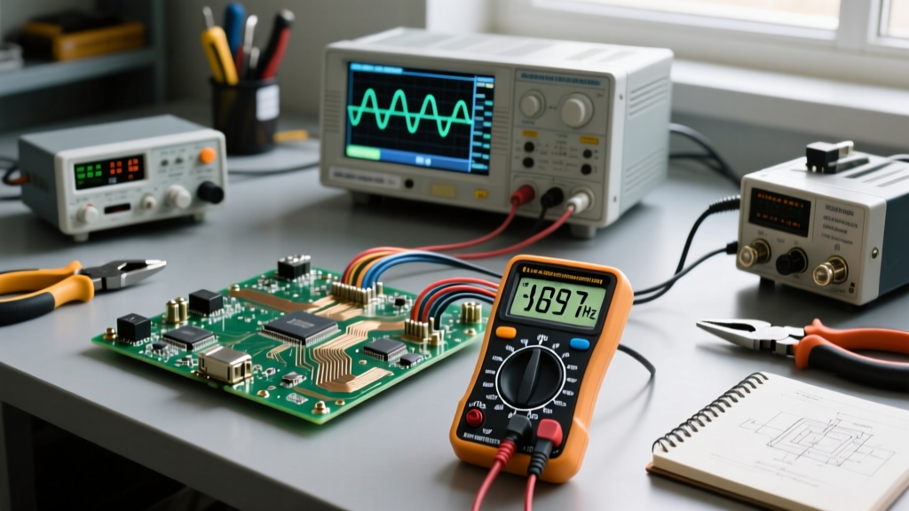
A Megohmmeter (commonly known by the brand name Megger) applies a high DC voltage (typically 500V or 1000V for low-voltage systems) between the conductor and the ground. It then measures the micro-amp leakage current passing through the insulator to calculate resistance.
According to the NETA (InterNational Electrical Testing Association) Acceptance Testing Specifications, the general rule of thumb for safe insulation resistance is a minimum of 1 Megohm per 1000V of operating voltage. However, modern XLPE and PVC cables in good condition should read in the hundreds of Megohms or even Gigaohms. A reading that drops significantly over time indicates moisture ingress, contamination, or thermal degradation, requiring immediate replacement before a ground fault occurs.
Essential Safety Protocols for Handling Conductors
Working with conductors requires strict adherence to safety protocols to prevent accidental energization and physical damage to the wire.
Lockout/Tagout (LOTO)
Before stripping, terminating, or testing any conductor, the circuit must be de-energized and secured. The OSHA Electrical Safety Standards mandate strict Lockout/Tagout procedures. Never assume a wire is dead based on a switch position; always verify the absence of voltage using a properly rated digital multimeter or non-contact voltage tester rated for the appropriate CAT level.
Proper Stripping Techniques
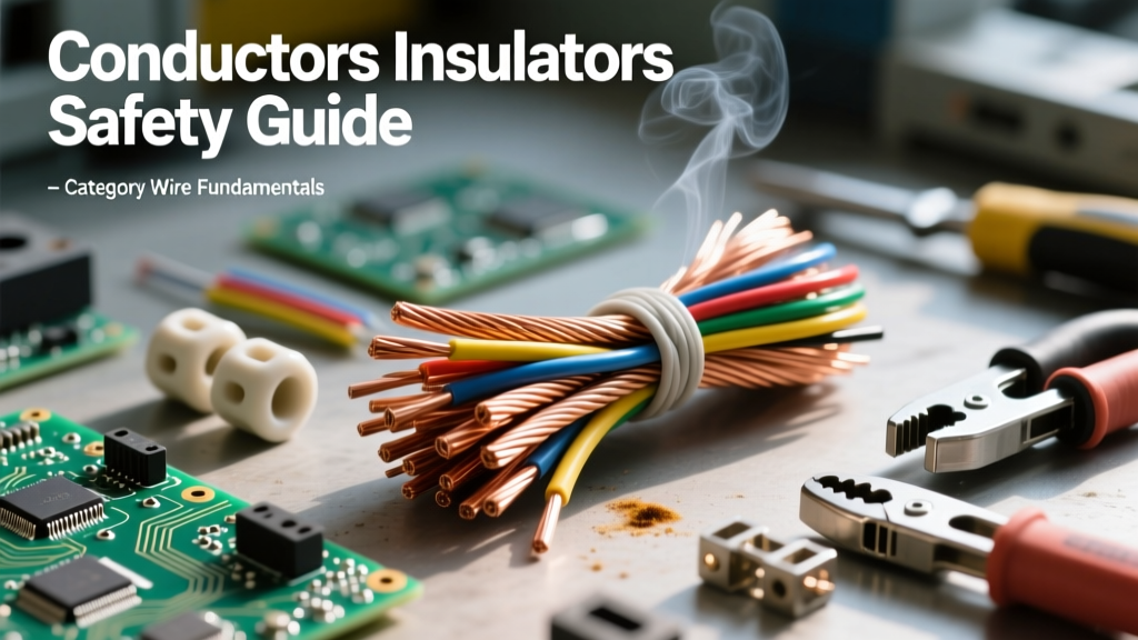
When removing insulation from a conductor, using a knife or improper stripping tool can easily 'nick' the copper or aluminum underneath. A nick creates a localized point of high mechanical stress and reduces the cross-sectional area of the conductor. Under heavy load, this nicked point will have higher resistance, generating a localized hot spot that can melt the surrounding insulation and start a fire inside a junction box. Always use calibrated, self-adjusting wire strippers sized exactly for the wire gauge.
Adherence to the National Electrical Code (NEC)
The NFPA 70 National Electrical Code dictates the allowable ampacity of conductors based on their insulation temperature rating and the ambient environment. Bundling too many current-carrying conductors in a single conduit prevents heat dissipation, effectively baking the insulation from the inside out. Always apply NEC derating factors when designing or modifying conduit runs.
Summary Checklist for DIY and Pro Electricians
- Verify Materials: Ensure lugs and terminals are rated for the specific conductor metal (Copper vs. Aluminum).
- Apply Antioxidants: Use approved pastes on all aluminum terminations to prevent galvanic corrosion.
- Respect Temperature Ratings: Do not terminate 90°C wire on devices rated only for 60°C without derating the ampacity.
- Test Before Touch: Always perform LOTO and verify zero voltage with a calibrated meter.
- Megger Test Critical Runs: Perform insulation resistance tests on long feeder runs or cables pulled through wet environments to detect hidden dielectric breakdown.
Understanding what are the conductors and insulators is not just an academic exercise; it is the foundation of electrical safety. By respecting the physical limits, thermal vulnerabilities, and environmental sensitivities of these materials, you can design and maintain systems that protect both property and human life.