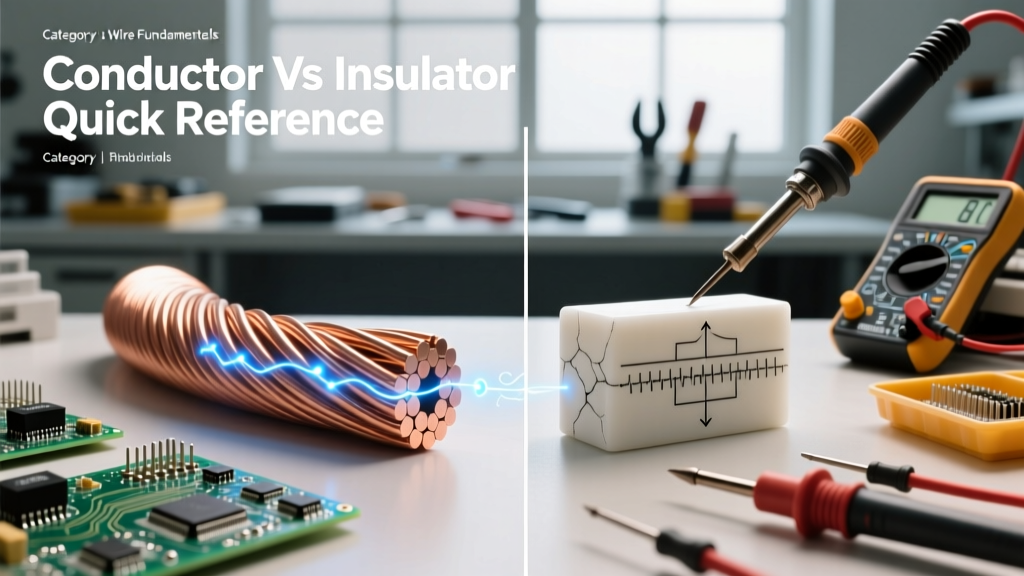

When electrical engineering students and DIY enthusiasts ask, 'what is the difference between a conductor and an insulator', the standard textbook answer is qualitative: conductors allow electrons to flow freely, while insulators block them. However, in real-world electrical design, wire sizing, and high-voltage troubleshooting, qualitative definitions are insufficient. To truly understand material behavior, we must look at the math.
This calculation tutorial moves beyond basic definitions. We will quantify the difference between conductors and insulators using quantum band gap energy, macro-scale resistivity calculations, leakage current math, and dielectric breakdown thresholds.
Quantum Mechanics: Calculating the Band Gap Energy
The fundamental difference between a conductor and an insulator begins at the atomic level, specifically within the electron band theory. The 'band gap' is the energy difference (in electron-volts, eV) between the top of the valence band (where electrons are bound to atoms) and the bottom of the conduction band (where electrons can move freely).
The Conductor (Copper Baseline)
In a conductor like copper (Cu), the valence and conduction bands overlap. Therefore, the band gap energy ($E_g$) is effectively zero.
- Band Gap ($E_g$): 0 eV
- Result: Electrons require virtually no external energy to enter the conduction band, allowing massive current flow even at low voltages.
The Insulator (PVC Jacket)
In an insulator like Polyvinyl Chloride (PVC), the band gap is massive. Electrons are tightly bound to their parent atoms.
- Band Gap ($E_g$): > 8.0 eV
- Result: It requires an extreme amount of energy to bridge this gap. Standard electrical potentials (120V to 600V) cannot provide the necessary energy to excite electrons across an 8.0 eV gap, resulting in near-zero current flow.
For deeper reading on the quantum mechanics of electrical conduction and band theory, refer to Georgia State University's HyperPhysics database.
Macro-Scale Math: Resistance vs. Leakage Current
To practically demonstrate what is the difference between a conductor and an insulator, we will calculate the resistance of a standard copper wire and compare it to the insulation resistance of its PVC jacket. We will use a 100-meter spool of 12 AWG copper wire with a 0.8 mm thick PVC insulation jacket.
Step 1: Conductor Resistance Calculation (12 AWG Copper)
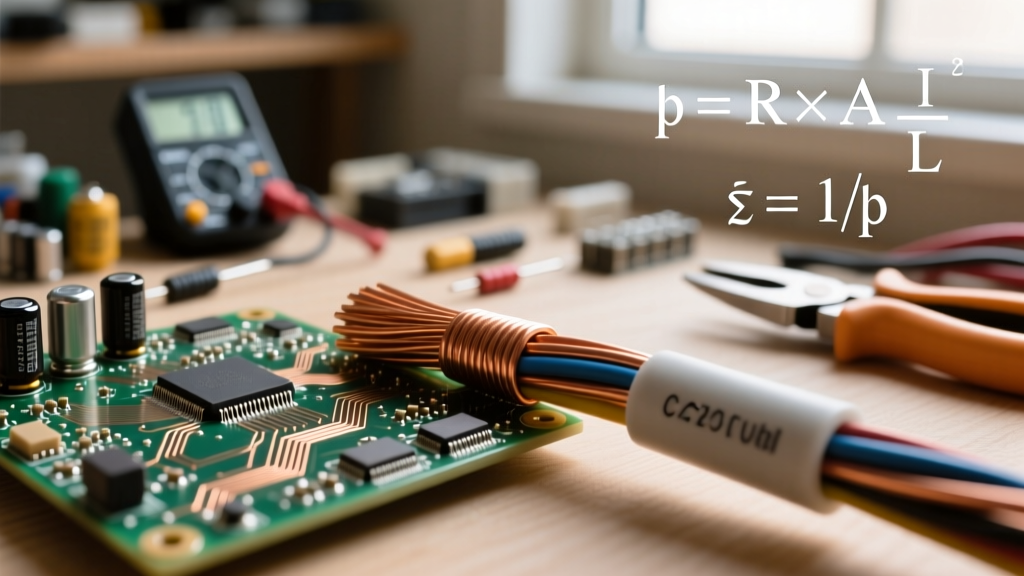
We use the standard resistivity formula: $R = \rho \frac{L}{A}$
- Resistivity of Copper ($\rho$): $1.68 \times 10^{-8} \, \Omega\cdot m$
- Length ($L$): 100 meters
- Cross-Sectional Area ($A$): 12 AWG has a diameter of 2.053 mm. Area = $\pi \times r^2 = 3.31 \times 10^{-6} \, m^2$
Calculation:
$R = (1.68 \times 10^{-8} \times 100) / (3.31 \times 10^{-6})$
$R = 0.507 \, \Omega$
The conductor offers barely half an ohm of resistance, allowing high current (up to 20 Amps) to pass with minimal voltage drop.
Step 2: Insulator Leakage Calculation (PVC Jacket)
Now, we calculate the resistance of the PVC insulation resisting current from the copper core to the outside environment. We use the same formula, but adapted for a cylindrical shell: $R_{ins} = \rho \frac{t}{A_{surface}}$
- Resistivity of PVC ($\rho$): $\approx 1.0 \times 10^{14} \, \Omega\cdot m$
- Thickness ($t$): 0.8 mm ($0.0008 \, m$)
- Surface Area ($A_{surface}$): $2 \times \pi \times r \times L = 2 \times \pi \times 0.001026 \, m \times 100 \, m = 0.645 \, m^2$
Calculation:
$R_{ins} = (1.0 \times 10^{14} \times 0.0008) / 0.645$
$R_{ins} = 1.24 \times 10^{11} \, \Omega$ (124 Gigaohms)
Step 3: Calculating Leakage Current
If we apply 120 Volts AC to this wire, how much current 'leaks' through the insulator? Using Ohm's Law ($I = V / R$):
$I = 120 \, V / 1.24 \times 10^{11} \, \Omega = 9.67 \times 10^{-10} \, A$
The leakage current is 0.96 nanoamps. This 13-order-of-magnitude difference in resistance is the mathematical proof of what separates a conductor from an insulator in practical wiring.
Dielectric Breakdown: Calculating the Failure Threshold
Insulators are not perfect; they fail when the electric field exceeds their dielectric strength. When an insulator fails, it temporarily becomes a conductor, resulting in a short circuit or arc flash.
The dielectric strength of standard rigid PVC is approximately 40 kV/mm. Let us calculate the breakdown voltage for our 0.8 mm thick 12 AWG wire jacket.
- Formula: $V_{breakdown} = \text{Dielectric Strength} \times \text{Thickness}$
- Calculation: $40 \, \text{kV/mm} \times 0.8 \, \text{mm} = 32 \, \text{kV}$ (32,000 Volts)
This means the PVC insulation will physically break down and allow catastrophic current flow if the voltage potential exceeds 32,000V. This calculation is critical for high-voltage engineering, demonstrating why standard 600V-rated THHN wire uses much thicker insulation or cross-linked polyethylene (XLPE) for medium-voltage applications.
Temperature Coefficient of Resistance (TCR) Calculations
Another vital difference is how these materials react to thermal changes. Conductors and insulators have opposite Temperature Coefficients of Resistance (TCR).
Conductor TCR (Positive)
As copper heats up, atomic lattice vibrations increase, scattering electrons and increasing resistance. The TCR ($\alpha$) for copper is $+0.00393 \, ^\circ\text{C}^{-1}$.
Formula: $R_T = R_0 [1 + \alpha(T - T_0)]$
If our 0.507 $\Omega$ wire heats up from 20°C to 80°C under load:
$R_{80} = 0.507 \times [1 + 0.00393(80 - 20)] = 0.507 \times 1.2358 = 0.626 \, \Omega$
The conductor's resistance increases by 23%, leading to higher $I^2R$ heat losses.
Insulator TCR (Negative)
Conversely, as insulators heat up, thermal energy helps electrons jump the band gap. Their resistance decreases as temperature rises. This is why thermal derating is mandatory in electrical panels; a hot insulator is a weaker insulator, increasing leakage current and the risk of dielectric failure.
Material Comparison Matrix
The table below summarizes the quantitative differences across common electrical materials, providing a rapid reference for wire sizing and material selection.
| Material | Classification | Resistivity ($\Omega\cdot m$) | Band Gap (eV) | Dielectric Strength (kV/mm) |
|---|---|---|---|---|
| Silver (Ag) | Conductor | $1.59 \times 10^{-8}$ | 0 (Overlap) | N/A |
| Copper (Cu) | Conductor | $1.68 \times 10^{-8}$ | 0 (Overlap) | N/A |
| Silicon (Si) | Semiconductor | $6.4 \times 10^{2}$ | 1.11 | N/A |
| Glass | Insulator | $10^{10}$ to $10^{14}$ | ~ 9.0 | 10 - 40 |
| PVC (Rigid) | Insulator | $10^{14}$ to $10^{15}$ | > 8.0 | ~ 40 |
| XLPE | Insulator | $> 10^{16}$ | > 8.5 | ~ 500 |
For comprehensive data on material properties and wiring standards, the All About Circuits textbook provides excellent foundational context on how these resistivity values translate to real-world circuit design.
Summary: The Engineering Perspective
Ultimately, answering 'what is the difference between a conductor and an insulator' requires looking at the numbers. A conductor is a material with a 0 eV band gap and a resistivity near $10^{-8} \, \Omega\cdot m$, designed to minimize voltage drop. An insulator is a material with an >8 eV band gap and a resistivity near $10^{14} \, \Omega\cdot m$, designed to restrict leakage current to the nanoamp scale and withstand high dielectric stress. By calculating these values, electrical engineers can accurately size wires, select appropriate jacket materials, and prevent catastrophic dielectric breakdowns in both low-voltage DIY projects and high-voltage industrial grids.