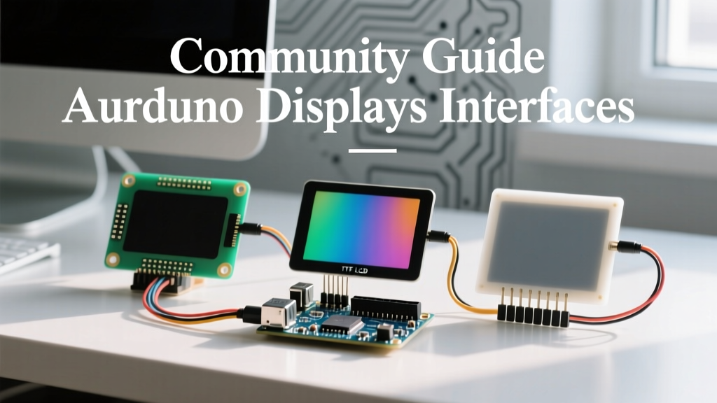

When navigating the vast ecosystem of Arduino displays, maker forums, GitHub issue trackers, and Discord channels are often the best places to find the unvarnished truth. While official datasheets provide theoretical maximums, the community knows which screens suffer from ghosting, which libraries consume too much SRAM, and which controller ICs are frequently counterfeited by overseas manufacturers. This community resource synthesizes years of crowdsourced troubleshooting into a definitive guide for selecting, wiring, and coding Arduino displays.
The Maker's Display Selection Matrix
Choosing the right display requires balancing resolution, interface speed, power consumption, and microcontroller compatibility. Below is a community-curated matrix of the most ubiquitous display technologies found in DIY electronics labs today.
| Display Tech | Common Controller | Interface | Avg Price (USD) | Best Community Use-Case |
|---|---|---|---|---|
| Monochrome OLED | SSD1306 (128x64) | I2C / SPI | $3.50 - $5.00 | Low-power sensor dashboards, wearable diagnostics |
| Color TFT LCD | ILI9341 (320x240) | SPI | $9.00 - $14.00 | Rich UI, oscilloscopes, retro-gaming consoles |
| IPS Color LCD | ST7789 (240x240) | SPI | $6.00 - $10.00 | High-contrast outdoor projects, smart home dials |
| E-Paper / E-Ink | Waveshare / Good Display | SPI | $12.00 - $25.00 | Ultra-low power data logging, price tags, weather stations |
Crowdsourced Pitfalls: What the Forums Warn About
If you spend enough time on the Arduino subreddit or the EEVblog forums, you will notice the same hardware pitfalls repeating. Understanding these failure modes before you wire your breadboard will save you hours of debugging and prevent destroyed components.
The 3.3V vs 5V Logic Level Trap
The most common casualty in beginner Arduino display projects is the SPI TFT screen. Most modern high-resolution TFT displays (like the ILI9341 or ST7789) operate strictly at 3.3V logic. If you connect a 5V ATmega328P (Arduino Uno/Nano) directly to the SPI pins (MOSI, SCK, CS, DC) of a 3.3V display, you are forcing 5V into silicon designed for a 3.6V absolute maximum rating.
The Community Fix: While some users report getting away with this temporarily due to internal protection diodes, it inevitably leads to degraded silicon and eventual failure. The recommended approach is to use a CD4050B non-inverting buffer or a BSS138 bidirectional logic level shifter. Note that the MISO line (data returning from the display) often does not require shifting, as the 3.3V HIGH output from the display usually exceeds the 2.4V threshold required for the ATmega328P to read a logic HIGH.
I2C Capacitance and Pull-Up Resistor Failures
The 0.96-inch SSD1306 I2C OLED is a staple in the maker community. However, many cheap clone boards omit the necessary 4.7kΩ pull-up resistors on the SDA and SCL lines, relying entirely on the microcontroller's internal weak pull-ups. This works on a short breadboard, but fails when you introduce ribbon cables.
Community Rule of Thumb: The I2C bus has a maximum capacitance limit of 400pF. Long wires act as capacitors. If your OLED displays garbage data or fails to initialize after adding 15cm of wire, add external 4.7kΩ pull-up resistors to the 3.3V or 5V rail near the display.
Library Ecosystem: Community Favorites vs. Official
The official libraries provided by manufacturers are often bloated, poorly optimized, or abandoned. The community has rallied behind several open-source alternatives that offer vastly superior performance and hardware support.
U8g2: The Monochrome Heavyweight
For OLEDs and monochrome LCDs, Olikraus's U8g2 Library Repository is the undisputed community champion. Unlike older libraries that require massive SRAM buffers (which easily exhaust the 2KB limit on an ATmega328P), U8g2 offers a 'Page Buffer' mode. This renders the display in horizontal slices, keeping the RAM footprint under 100 bytes. The trade-off is a steeper learning curve and slightly slower refresh rates, but for static dashboards, it is unparalleled. U8g2 also includes hundreds of embedded fonts, including Unicode and Cyrillic support, which is a massive information gain for international makers.
TFT_eSPI: Unleashing ESP32 DMA
When driving color TFTs on 32-bit microcontrollers like the ESP32, Bodmer's TFT_eSPI GitHub repository is mandatory. The library's secret weapon is its utilization of the ESP32's SPI DMA (Direct Memory Access) controller. By offloading the pixel-pushing to the DMA hardware, the main CPU is freed to handle Wi-Fi stacks and sensor polling. Configuring TFT_eSPI requires editing the User_Setup.h file to define your exact pinout and display driver, a step that frustrates beginners but yields frame rates up to 10x faster than standard Adafruit equivalents.
Adafruit_GFX: The Reliable Baseline
Despite the rise of optimized alternatives, the Adafruit GFX Guide remains the community's fallback for rapid prototyping. Its standardized coordinate system and primitive drawing functions (lines, circles, rounded rectangles) are universally understood. If you are porting code from an old project or need a quick proof-of-concept, GFX is the safest starting point.
Real-World Wiring: SPI Pin Mapping Across MCUs
One of the most frequent questions on maker forums involves SPI pin mapping when migrating a display from an Arduino Uno to a more powerful board. Hardware SPI pins are hardcoded into the silicon of the microcontroller. Using software (bit-banged) SPI will work, but it will cripple your display's frame rate.
| Microcontroller | MOSI (SDA) | MISO (SDO) | SCK (SCL) | Default SS (CS) |
|---|---|---|---|---|
| Arduino Uno / Nano (ATmega328P) | Pin 11 | Pin 12 | Pin 13 | Pin 10 |
| Arduino Mega 2560 | Pin 51 | Pin 50 | Pin 52 | Pin 53 |
| ESP32 (Default VSPI) | GPIO 23 | GPIO 19 | GPIO 18 | GPIO 5 |
| Raspberry Pi Pico (RP2040 SPI0) | GP19 (TX) | GP16 (RX) | GP18 (SCK) | GP17 (CSn) |
Community Tip: On the ESP32, you can remap SPI pins to almost any GPIO using the GPIO matrix, but doing so disables the ultra-fast IOMUX hardware routing and can introduce slight timing jitter at clock speeds above 40MHz. Always try to use the default VSPI or HSPI pins for high-resolution TFTs.
Sourcing and the Counterfeit Controller IC Problem
A deeply discussed topic in advanced maker circles is the prevalence of cloned and recycled controller ICs in budget Arduino displays. When you buy a $6 ST7789 display from an online marketplace, you are rarely getting a genuine Sitronix chip.
The 'Red Tab' vs 'Black Tab' Initialization Quirks
Cloned ST7735 and ST7789 controllers often have inverted color registers or misaligned memory access control (MADCTL) settings. A common symptom is a display that turns on but shows inverted colors (black becomes white, red becomes cyan) or features a 20-pixel vertical offset where the image bleeds off the edge of the glass.
To fix this, the community relies on sending specific initialization commands during the setup() routine. For inverted colors, sending the INVON (0x21) or INVOFF (0x20) command via raw SPI can instantly correct the palette. For offset issues, modifying the X and Y initialization offsets in your library's header file (e.g., changing TFT_WIDTH and TFT_HEIGHT boundaries or applying a setRotation() offset) is the standard workaround. Always check the GitHub issues tab of your chosen library for 'offset' or 'color invert' threads specific to your exact display vendor.
E-Paper Refresh Times and Ghosting
When working with Waveshare or Good Display e-Paper modules, newcomers often complain about 'ghosting' (faint remnants of previous frames). The community consensus is that you must perform a 'full refresh' (which flashes the screen black and white) every 5 to 10 'partial updates'. Partial updates are faster and prevent eye strain from flashing, but they slowly degrade the electrophoretic ink alignment. Furthermore, always ensure you put the e-Paper display into deep sleep mode via the SLEEP command after updating; leaving the SPI bus active or the power rails energized will drain your battery and degrade the ink capsules over time.
By leveraging these community-tested insights—respecting logic levels, choosing the right library for your silicon, and anticipating counterfeit IC quirks—you can bypass the most frustrating hurdles in display integration and focus on building robust, professional-grade interfaces.