
The Physics of Optical Color Detection
At its core, a color sensor is an optical transducer that converts reflected light photons into measurable electrical signals. Unlike a standard camera that uses a Bayer filter matrix over millions of microscopic pixels, a dedicated color sensor utilizes an array of silicon photodiodes covered by precise optical interference filters. These filters are tuned to specific wavelength bands—typically Red (610nm), Green (540nm), Blue (465nm), and Clear (broadband visible).
Silicon, by its natural crystalline properties, is highly sensitive to near-infrared (NIR) light, peaking around 900nm. If left unfiltered, NIR contamination will completely skew the RGB ratios, making a dark red object appear identical to a black one. Therefore, high-quality color sensor ICs integrate an advanced IR-blocking filter directly into the glass package. Understanding this underlying physics is the first step to mastering optical sorting, fluid analysis, and automated quality control in your DIY electronics projects.
Comparing Popular Color Sensor ICs
Choosing the right integrated circuit depends entirely on your required spectral resolution and microcontroller interface. Below is a technical comparison of the three most dominant architectures in the maker and prototyping space.
| IC Model | Architecture | Interface | Channels | Best Application |
|---|---|---|---|---|
| TCS3200 | Programmable Frequency | GPIO (Pulse) | 4 (RGB + Clear) | Basic sorting, legacy Arduino projects |
| TCS34725 | I2C Digital w/ IR Block | I2C (0x29) | 4 (RGB + Clear) | Standard RGB detection, LED feedback |
| AS7341 | Spectrometer (OFA) | I2C (0x39) | 11 (8 Vis, NIR, Clear) | Fluid spectroscopy, precise hue matching |
The TCS3200 is an older architecture that outputs a square wave frequency proportional to light intensity. While easy to read with a microcontroller's pulseIn() function, it requires 8 GPIO pins and lacks an integrated IR-blocking filter, making it highly susceptible to ambient sunlight errors.
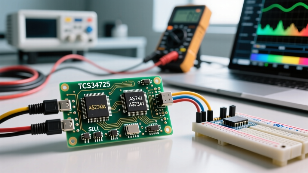
The TCS34725 is the modern hobbyist standard. As detailed in the Adafruit Color Sensor Guide, it communicates over I2C and features a built-in IR rejection filter and an onboard white LED for controlled illumination. For advanced users requiring true spectral data rather than broad RGB buckets, the AS7341 acts as a miniature spectrometer. According to the SparkFun AS7341 Hookup Guide, its Optical Filter Array (OFA) isolates specific nanometer bands (e.g., F1 at 415nm, F8 at 680nm), allowing you to detect chemical concentrations or subtle dye variations that a standard RGB sensor would completely miss.
I2C Wiring Blueprint and Hardware Quirks
When wiring an I2C-based color sensor like the TCS34725 to a 3.3V or 5V microcontroller, power delivery and signal integrity are paramount. Most breakout boards include a 3.3V LDO voltage regulator, allowing you to safely power the board from a 5V Arduino Uno. However, the I2C data (SDA) and clock (SCL) lines require careful attention to pull-up resistors.
The Pull-Up Resistor Trap
I2C is an open-drain protocol. It requires pull-up resistors to pull the signal line high. Most commercial breakout boards include 10kΩ pull-up resistors on the SDA and SCL lines. If you are daisy-chaining multiple sensors or using long jumper wires (over 12 inches), the parasitic capacitance of the wire will round off the square wave edges, causing I2C bus lockups and corrupted color data.
- Short runs (< 6 inches): Rely on the breakout board's 10kΩ resistors.
- Long runs or noisy environments: Add external 4.7kΩ pull-up resistors to the 3.3V line near the microcontroller to stiffen the bus.
- Address Conflicts: The TCS34725 is hardcoded to I2C address
0x29. If you need two sensors on one bus, you must use an I2C multiplexer like the TCA9548A.
Mastering Integration Time and Gain
The most common reason a color sensor fails in a real-world deployment is improper configuration of the Integration Time (ATIME) and Gain (AGAIN) registers. These two variables dictate the analog-to-digital conversion of the photodiode current.
Integration Time is the duration the photodiodes are allowed to collect photons before the ADC reads the voltage. It is configured in steps of 2.4ms. A value of 0xFF (2.4ms) is extremely fast but yields low resolution in dim environments. A value of 0x00 (700ms) gathers massive amounts of light data but introduces severe latency. If the integration time is too long for a bright object, the ADC will saturate, clipping at the maximum 16-bit value of 65,535 counts. Once a channel clips, your color ratio math is permanently ruined until the exposure is reduced.
Gain acts as an analog multiplier before the ADC. Available settings are typically 1x, 4x, 16x, and 60x. You should always default to 1x gain and only increase it if you are operating in a heavily shrouded, low-light environment. Pushing 60x gain in a well-lit room will instantly saturate the sensor and introduce excessive analog noise.
Expert Calibration Framework: Never rely on raw ADC counts. To achieve accurate color matching, you must implement a White Balance matrix. Place a pure PTFE (Teflon) or matte white calibration card under the sensor's LED. Record the Clear, R, G, and B values. Divide all subsequent target readings by these baseline white values to generate a normalized 0.0 to 1.0 ratio. This eliminates hardware variance and LED color temperature drift.
Overcoming Real-World Optical Failure Modes
Even with perfect I2C wiring and calibrated integration times, physical optics will introduce errors if you ignore the geometry of light reflection.
Specular vs. Diffuse Reflection Errors
Color sensors are designed to measure diffuse reflection—light that penetrates the surface of an object, interacts with the pigment, and scatters back. However, if you place the sensor directly perpendicular (90 degrees) to a glossy object (like a polished M&M, a LEGO brick, or a PCB solder mask), the onboard white LED will cause specular reflection. The sensor will simply read the blinding white light of its own LED bouncing off the glossy surface, reporting the object as pure white regardless of its actual pigment.
The Fix: Mount the color sensor at a 30 to 45-degree offset angle from the target surface. Alternatively, place a piece of cross-polarized optical film over both the LED and the sensor aperture to physically block direct specular glare while allowing diffuse scattered light to pass through.
Ambient Light Rejection (ALS)
If your sorting machine operates near a window, 50Hz/60Hz flicker from overhead fluorescent lights or shifting sunlight will introduce massive variance into your RGB readings. The TCS34725 handles this via its internal oscillator, but you must ensure your integration time is a multiple of the AC mains period. Setting your integration time to 100ms or 120ms effectively averages out the 50Hz/60Hz ripple from artificial room lighting, resulting in rock-solid color consistency regardless of the time of day.