
The Transducer Divide: Electret vs. MEMS
When building DIY audio projects, clapping switches, or voice-activated IoT devices, the sound sensor module you choose dictates your entire signal chain. Most beginner kits include a generic microphone module, but treating all sound sensors as interchangeable is a critical mistake. The market is broadly split into two transducer technologies: traditional Electret Condenser Microphones (ECM) and modern Micro-Electro-Mechanical Systems (MEMS).
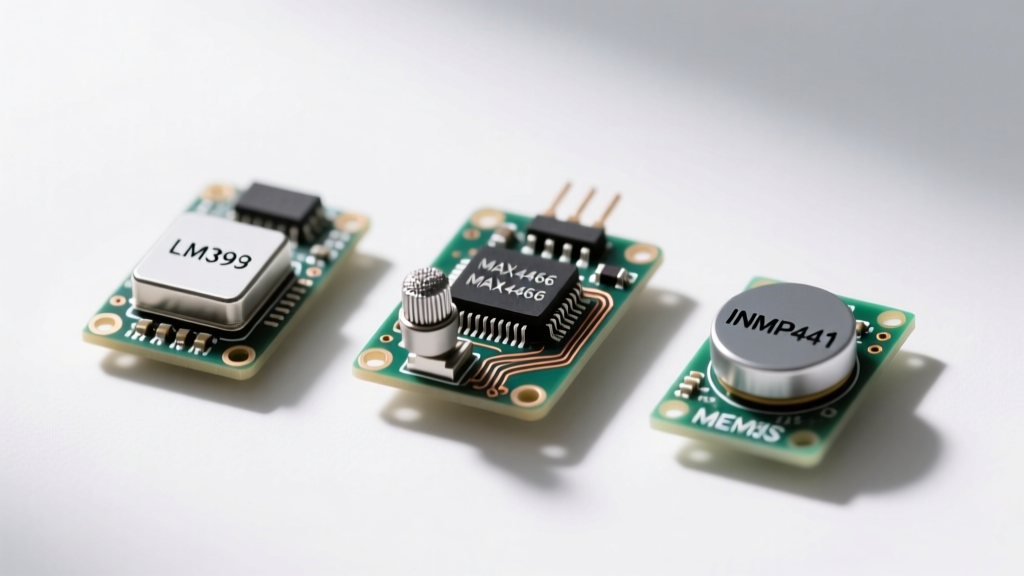
Electret sensors, found in the ubiquitous KY-038 and MAX4466 breakouts, rely on a physical diaphragm and a permanently charged dielectric material. They are analog by nature, require bias voltage, and are highly susceptible to electromagnetic interference (EMI). Conversely, MEMS microphones like the INMP441 are etched directly onto silicon wafers. They offer vastly superior signal-to-noise ratios (SNR), flat frequency responses, and often feature built-in analog-to-digital converters (ADCs) that output pristine I2S data streams.
Pro-Tip: If your project involves simply detecting a loud noise (like a knock or clap), an analog comparator circuit is sufficient. If you are sampling audio for FFT analysis, speech-to-text, or streaming, you must bypass analog sensors entirely and use an I2S MEMS module.
Sound Sensor Module Comparison Matrix
Below is a benchmark of the most common sound sensor modules found in Arduino, ESP32, and Raspberry Pi Pico starter kits, evaluated on interface type, audio fidelity, and microcontroller compatibility.
| Module / IC | Transducer Type | Output Interface | SNR / Sensitivity | Best Application | Est. Price |
|---|---|---|---|---|---|
| LM393 (KY-038) | Electret | Analog / Digital (Comparator) | ~45 dB / -42 dB | Clap switches, noise triggers | $1.50 |
| MAX4466 | Electret | Analog (Amplified) | ~55 dB / Adjustable Gain | Audio envelopes, VU meters | $4.00 |
| INMP441 | MEMS | Digital (I2S) | 61 dB / -26 dBFS | Voice AI, ESP32 audio streaming | $2.50 |
| SPH0645LM4H | MEMS | Digital (I2S) | 65 dB / -21 dBFS | Hi-Fi stereo recording | $5.00 |
Deep Dive: Analog Threshold Sensors (LM393 & KY-037)
The LM393-based sound sensors are the most abundant modules in 37-in-1 sensor kits. They feature an electret microphone coupled with an LM393 dual differential comparator. These boards typically expose four pins: VCC, GND, AO (Analog Out), and DO (Digital Out).
How the Comparator Circuit Works
The DO pin is tied to a blue trimpot on the board. This potentiometer sets a voltage threshold. When the raw audio signal from the electret capsule exceeds this threshold, the LM393 flips the DO pin from HIGH to LOW (or vice versa, depending on the board revision). This makes the module excellent for sound-activated relays where you only care if a noise occurred, not what the noise was.
The Analog Out (AO) Pitfall
Many beginners attempt to use the AO pin to sample actual audio waveforms using an Arduino analogRead() function. This usually results in heavy clipping and unusable data. The onboard amplifier is not designed for linear audio reproduction; it is designed to swing rails for the comparator. Furthermore, the AO signal is biased near ground, meaning the negative half of the audio wave is simply chopped off by the microcontroller 0V ADC floor. For true audio sampling, you need a biased amplifier.
Sampling Audio Envelopes: The MAX4466 Breakout
If your project requires measuring the volume or amplitude of sound over time—such as building an LED VU meter or a reactive light show—the MAX4466 electret amplifier breakout is the gold standard for analog hobbyists.
Unlike the raw LM393, the MAX4466 is a dedicated microphone preamplifier. Its most critical feature for microcontroller integration is the DC bias. The chip outputs a quiescent voltage of exactly VCC/2. If you power it with 5V, the silence baseline sits at 2.5V. When sound waves hit the diaphragm, the voltage oscillates above and below 2.5V. This perfectly aligns with the Arduino 0-5V ADC window, allowing you to capture the full positive and negative phases of the audio wave.
- Gain Adjustment: The board includes a tiny surface-mount or through-hole resistor that dictates the gain (typically 25x to 125x). Modifying this resistor is often necessary if your sound source is too quiet or too loud.
- Power Supply Rejection Ratio (PSRR): The MAX4466 excels at rejecting power supply noise, meaning the hiss from your Arduino 5V regulator will not bleed heavily into your audio signal.
The I2S Revolution: INMP441 MEMS for Voice AI
With the rise of edge-computing and local voice assistants on the ESP32, analog microphones are no longer sufficient. The noise floor of an ESP32 internal ADC, combined with the EMI generated by its Wi-Fi radio, makes analog audio sampling a frustrating exercise in noise reduction. Enter the INMP441 I2S MEMS sound sensor.
The INMP441 contains the microphone capsule, the preamp, and a sigma-delta ADC all on a single silicon die. It outputs a 24-bit digital audio stream via the I2S (Inter-IC Sound) protocol. Because the signal remains digital from the exact moment it leaves the capsule, it is completely immune to the analog noise injection that plagues electret microphones.
Crucial Wiring Detail: The L/R Pin
The most common failure mode when wiring the INMP441 to an ESP32 is misunderstanding the L/R (Left/Right) channel selection pin. I2S is inherently a stereo protocol, transmitting two channels on a single data line. The INMP441 must be told which channel to occupy.
- If you tie the L/R pin to GND, the microphone outputs data on the Left Channel (when the Word Select / LRCLK line is LOW).
- If you tie the L/R pin to VDD (3.3V), it outputs on the Right Channel.
If you configure your ESP32 I2S driver to read the Left channel, but the hardware L/R pin is floating or tied high, your audio buffer will fill with zeros or static. Always verify your L/R pin strapping against your ESP-IDF or Arduino I2S library configuration.
For comprehensive I2S peripheral configuration on Espressif chips, consult the official ESP-IDF I2S API Reference to ensure your DMA buffers and sample rates match the INMP441 operational sweet spot.
Troubleshooting Hiss, Hum, and Ground Loops
Even with the right module, DIY audio projects are notorious for 50Hz/60Hz mains hum and high-frequency switching noise. Here is a practical troubleshooting framework for cleaning up your sound sensor signal chain:
- Decoupling Capacitors: Always solder a 100nF ceramic capacitor and a 10µF electrolytic capacitor directly across the VCC and GND pins of your analog sensor module. This creates a local energy reservoir and shunts high-frequency noise to ground.
- Twisted Pair Wiring: When running analog audio signals from a MAX4466 to a microcontroller, twist the signal wire and the ground wire together. This minimizes the loop area, drastically reducing the antenna effect that picks up EMI from nearby servos or relays.
- Star Grounding: Never daisy-chain the ground connections of your sound sensor, your microcontroller, and high-current loads like LED strips. Route all grounds to a single central point to prevent ground loops, which manifest as a low-frequency hum in your audio data.
For those designing custom PCBs integrating MEMS microphones, the acoustic port placement and cavity resonance are just as critical as the electrical routing. As detailed in the Analog Devices guide on MEMS microphone design, improper acoustic sealing can ruin the low-frequency response of an otherwise perfect digital sensor.
Final Verdict: Which Kit Should You Buy?
Your choice of sound sensor must align strictly with your project data requirements. If you are building a simple knock-to-unlock servo box or a clap-activated lamp, grab a multi-pack of LM393 KY-038 modules. They are cheap, digital, and require minimal coding.
If you are building reactive lighting, audio visualizers, or need to measure ambient decibel levels, invest in the MAX4466. Its DC-biased analog output makes Arduino ADC sampling mathematically straightforward.
Finally, if you are stepping into the world of ESP32 voice assistants, offline wake-word detection, or IP audio streaming, skip the analog era entirely. The INMP441 I2S MEMS module is mandatory. Its digital noise immunity and 24-bit resolution provide the clean audio floor required by modern machine learning models. For further reading on handling MEMS acoustics in embedded systems, check out the SparkFun MEMS Microphone Hookup Guide.