
Selecting the correct conductor is the single most critical decision in any electrical installation. Relying on guesswork or outdated rules of thumb doesn't just lead to tripped breakers; it creates severe fire hazards due to thermal runaway and insulation meltdown. Whether you are wiring a 200-amp residential service, a 50-amp RV pedestal, or a low-voltage DIY microcontroller project, understanding how to read and apply a wire sizes chart is non-negotiable. This comparison guide breaks down the complexities of the American Wire Gauge (AWG) system, metric cross-sections, material differences, and the hidden insulation variables that dictate real-world ampacity.
Decoding the Standard Wire Sizes Chart: AWG vs. Metric (mm²)
The North American electrical industry relies on the AWG system, standardized by ASTM B258. Conversely, the International Electrotechnical Commission (IEC 60228) uses nominal cross-sectional area measured in square millimeters (mm²). A common point of failure for international DIYers and engineers is assuming these systems map perfectly to one another. They do not.
The AWG system is logarithmic. A decrease of three gauge numbers results in a doubling of the cross-sectional area, while a decrease of ten gauge numbers multiplies the area by exactly ten. Metric sizing, however, uses standardized stepped tiers (1.5, 2.5, 4, 6, 10 mm²). Below is a comparative wire sizes chart mapping the most common residential and commercial conductor sizes.
| AWG Size | Metric Equivalent (mm²) | Diameter (Inches) | Circular Mils (CM) | Standard Copper Ampacity (75°C) |
|---|---|---|---|---|
| 14 AWG | ~2.08 (Use 2.5 mm²) | 0.0641 | 4,110 | 15 Amps |
| 12 AWG | ~3.31 (Use 4.0 mm²) | 0.0808 | 6,530 | 20 Amps |
| 10 AWG | ~5.26 (Use 6.0 mm²) | 0.1019 | 10,380 | 30 Amps |
| 8 AWG | ~8.37 (Use 10 mm²) | 0.1285 | 16,510 | 40 Amps |
| 6 AWG | ~13.30 (Use 16 mm²) | 0.1620 | 26,240 | 55 Amps |
| 4 AWG | ~21.15 (Use 25 mm²) | 0.2043 | 41,740 | 70 Amps |
| 2 AWG | ~33.62 (Use 35 mm²) | 0.2576 | 66,360 | 95 Amps |
Pro Tip: When substituting metric wire for AWG in North America, always round up to the next available AWG equivalent to ensure you do not violate the National Electrical Code (NEC) ampacity requirements.
Copper vs. Aluminum: How Material Shifts the Chart
A standard wire sizes chart usually defaults to copper conductors. However, aluminum is frequently used for high-amperage feeders (like 200A service entrances) due to its lower cost and lighter weight. When transitioning from copper to aluminum, the chart shifts dramatically.
The Sizing Rule of Thumb
Because aluminum has roughly 61% the conductivity of copper by volume, an aluminum conductor must be physically larger to carry the same current without overheating. The industry standard practice is to increase the wire size by two AWG steps when switching from copper to aluminum. For example, if a load requires 4 AWG copper (rated for 70A at 75°C), you must use 2 AWG aluminum (rated for 90A at 75°C) to safely carry the same 70A load.
Furthermore, the NEC strictly mandates that aluminum conductors used in branch circuits and feeders must be of the AA-8000 series alloy. Older, pure aluminum wiring (pre-1970s) suffered from creep and thermal expansion issues at termination points, leading to arcing and fires. Modern AA-8000 alloys mitigate this, but you must still apply an anti-oxidant compound (like Noalox) to aluminum terminations to prevent galvanic corrosion when connecting to copper lugs.
The Insulation Trap: Why 90°C Wire Acts Like 75°C
One of the most misunderstood aspects of reading a wire sizes chart involves insulation temperature ratings. Modern building wires, such as THHN/THWN-2 and XHHW-2, feature insulation rated for 90°C. Looking at the 90°C column of the NEC ampacity tables, a 10 AWG copper wire appears capable of handling 40 amps. So why do electricians universally protect 10 AWG wire with a 30-amp breaker?
Termination Temperature Rules (NEC 110.14(C))
The bottleneck in any circuit is rarely the wire itself; it is the termination point. Standard circuit breakers, receptacles, and panel lugs are typically rated for a maximum of 75°C. According to NFPA 70 (National Electrical Code) Section 110.14(C), the ampacity of a conductor must be selected based on the lowest temperature rating of any connected device, termination, or conductor in the circuit.
- The 60°C Column: Used for circuits rated 100A or less, unless the equipment is specifically marked otherwise (common in older homes or specific lighting fixtures).
- The 75°C Column: The standard baseline for almost all modern residential and commercial terminations.
- The 90°C Column: Used almost exclusively for derating calculations (e.g., when bundling more than three current-carrying conductors in a single raceway or adjusting for high ambient attic temperatures).
Therefore, while you buy 90°C THHN wire for its superior derating capabilities, you must still use the 75°C column on the wire sizes chart to determine your final overcurrent protection size.
Beyond the Chart: Calculating for Voltage Drop
A standard ampacity chart assumes a short run length. It tells you the wire's thermal limit, but it completely ignores voltage drop. If you push 50 amps through 150 feet of 6 AWG copper wire, the wire won't melt, but the voltage at the destination will sag significantly, potentially damaging sensitive electronics or causing motors to overheat.
The NEC recommends a maximum voltage drop of 3% for branch circuits and 5% overall from the utility to the furthest outlet. To calculate this, electrical engineers use the following formula:
VD = (2 × K × I × L) / CM
- VD: Voltage Drop
- K: Direct Current Constant (12.9 for Copper, 21.2 for Aluminum at 75°C)
- I: Current in Amps
- L: One-way length of the wire in feet
- CM: Circular Mils of the conductor (found on the wire sizes chart)
Real-World Scenario: 50A RV Pedestal at 120 Feet
Imagine you are installing a 240V, 50-amp RV receptacle located 120 feet from the main panel. Let's test 6 AWG Copper against the 3% rule (Maximum allowable drop = 7.2 Volts).
- VD = (2 × 12.9 × 50 × 120) / 26,240
- VD = 154,800 / 26,240 = 5.9 Volts
- Percentage Drop = (5.9 / 240) × 100 = 2.45%
Because 2.45% is under the 3% threshold, 6 AWG copper is perfectly acceptable here. If you had attempted to use 8 AWG copper (CM = 16,510), the drop would be 9.3 Volts (3.8%), which fails the efficiency standard and requires upsizing the wire, despite 8 AWG technically being rated for higher amperage in short runs. For complex routing, utilizing a dedicated Southwire Voltage Drop Calculator can automate these circular mil calculations.
Stranded vs. Solid Conductors: Does the Chart Change?
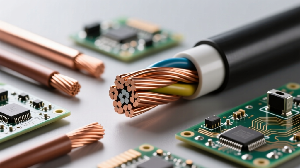
A frequent question when consulting a wire sizes chart is whether the physical construction of the wire—solid versus stranded—alters its ampacity. From a strict NEC thermal perspective, the ampacity remains identical for a given AWG size regardless of stranding. A 10 AWG solid wire and a 10 AWG stranded wire have the exact same cross-sectional area of copper and the same thermal limits.
However, their physical applications differ vastly. Solid wire is rigid, cheaper, and easier to terminate under standard residential screw terminals. Stranded wire is mandatory for environments subject to vibration (like automotive or marine applications) or for pulling through conduit with multiple bends, as its flexibility drastically reduces friction and the risk of insulation tearing. For high-frequency AC applications or DC battery banks, stranded (or even fine-stranded welding cable) is preferred to mitigate the skin effect and reduce termination fatigue.
Summary Checklist for Sizing Conductors
Before purchasing wire or pulling a permit, run your project through this final checklist:
- Identify the Load: Calculate continuous (125% multiplier) vs. non-continuous loads.
- Consult the Chart: Match the amperage to the 75°C copper column for standard terminations.
- Check Material: If using aluminum, increase the AWG size by two steps and use anti-oxidant paste.
- Calculate Voltage Drop: If the run exceeds 50 feet, run the VD formula to ensure you aren't starving the appliance of voltage.
- Verify Conduit Fill: Ensure your chosen wire size doesn't exceed the 40% conduit fill capacity mandated by NEC Chapter 9.
By treating the wire sizes chart not as a simple lookup table, but as a dynamic engineering tool that accounts for material, insulation, and distance, you guarantee an electrical system that is both inherently safe and highly efficient.