
The Anatomy of an Automotive-Grade Position Sensor
When engineers design throttle position sensors (TPS), accelerator pedal modules, or HVAC blend-door actuators, a standard carbon-track potentiometer will fail within weeks. The under-hood and under-dash automotive environments are brutal, characterized by extreme thermal cycling, high-frequency vibration, and corrosive humidity. To survive, designers must turn to specialized automotive potentiometers, typically utilizing conductive plastic or advanced cermet elements.
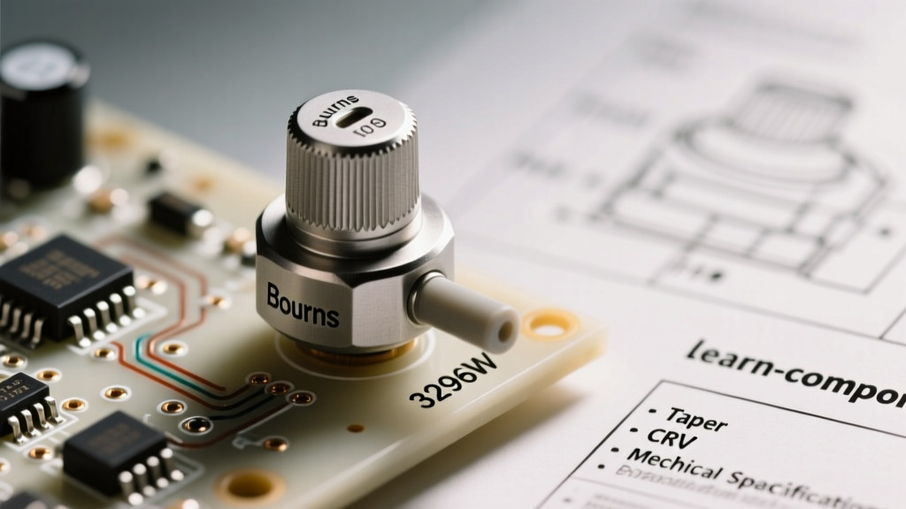
Reading a datasheet for an automotive-grade component requires looking past the basic resistance and tolerance values. You must scrutinize mechanical lifecycle ratings, Contact Resistance Variation (CRV), and environmental sealing metrics. In this breakdown, we will dissect the critical parameters found in premium conductive plastic datasheets, such as the Bourns Conductive Plastic Portfolio, and explain how these specs translate to real-world ECU reliability.
Material Science: Why Conductive Plastic Dominates
Before diving into the electrical tables, it is vital to understand the resistive element material. Standard potentiometers use carbon composition or wirewound tracks. Automotive position sensors almost exclusively rely on conductive plastic or cermet (ceramic-metal composite).
Conductive Plastic vs. Cermet
Conductive plastic tracks are created by mixing carbon or metal powders into a polymer resin. This yields an incredibly smooth surface, allowing the wiper to glide with minimal friction. The result is a mechanical life rating that often exceeds 5,000,000 cycles, making it the undisputed king for pedal and throttle applications where the wiper is in constant motion.
Cermet tracks, while offering better temperature stability and higher power dissipation, are rougher. They typically max out around 1,000,000 cycles and are better suited for under-hood trimmers or low-actuation sensors like fluid level floats.
| Parameter | Conductive Plastic (e.g., Bourns 3540/3543) | Cermet Trimmer | Carbon Composition |
|---|---|---|---|
| Typical Cycle Life | 5,000,000+ cycles | 200 - 1,000,000 cycles | 10,000 - 100,000 cycles |
| Wiper Noise (CRV) | Extremely Low (< 2% of R) | Moderate (Up to 3% of R) | High (Prone to spikes) |
| Linearity | ±0.25% to ±0.5% | ±0.5% to ±1.0% | ±5% to ±20% |
| Temp Coefficient | ±1000 ppm/°C | ±100 ppm/°C | Highly Variable |
| Primary Auto Use Case | Throttle, Pedal, Steering Angle | Headlight Aim, Trim Calibration | Consumer Audio (Non-Auto) |
Datasheet Deep Dive: Critical Parameters Decoded
When you open a datasheet for an automotive position sensor, three specific parameters dictate whether the part will pass OEM validation testing.
1. Contact Resistance Variation (CRV) and Wiper Bounce
CRV measures the maximum change in resistance between the wiper and the track as the shaft is rotated. In a 5V ECU circuit reading a 10kΩ potentiometer, a momentary loss of wiper contact (wiper bounce) causes the ADC input to float or spike to 5V. This micro-second spike can trick the Engine Control Unit into registering an OBD-II P0121 (Throttle/Pedal Position Sensor Circuit Range/Performance) fault code, putting the vehicle into limp mode.
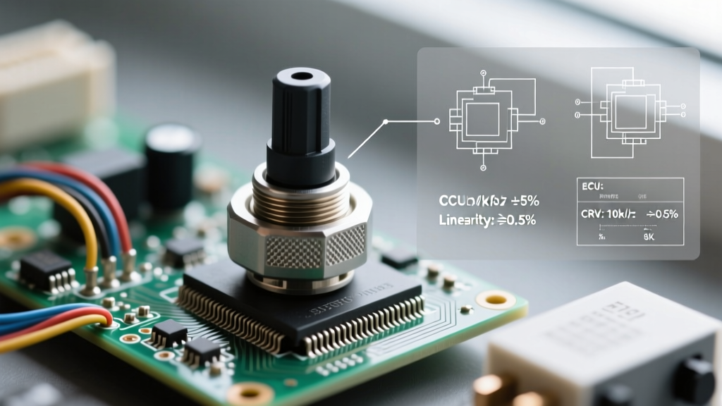
High-quality automotive datasheets will specify a CRV of ≤ 2% of the total resistance or a hard ohmic limit (e.g., ≤ 50Ω). If the datasheet only lists 'End-to-End Resistance' without a CRV or 'Output Smoothness' metric, the part is not suitable for dynamic automotive sensing.
2. Independent Linearity
Linearity defines how closely the actual voltage output matches a theoretically perfect straight line. Datasheets usually specify Independent Linearity, which is the maximum deviation from the best-fit straight line, regardless of the terminal resistances. For drive-by-wire throttle bodies, an independent linearity of ±0.25% is standard. This ensures that a 1mm pedal depression yields a perfectly predictable voltage increase, allowing the ECU to map fuel injection accurately without complex software calibration curves.
3. Dielectric Withstanding Voltage
You might wonder why a sensor operating on a 5V logic rail needs a dielectric withstand rating of 500 VAC or 900 VDC. Automotive environments are plagued by load-dump transients, inductive kickback from fuel injectors, and ESD events from passengers entering the cabin. A high dielectric rating ensures that a massive transient spike on the chassis ground does not arc through the potentiometer's internal substrate, permanently destroying the resistive track.
Real-World Failure Modes in the Field
Even the best automotive potentiometers fail if the mechanical housing or electrical integration is flawed. Understanding these failure modes helps in designing robust PCB layouts and mechanical enclosures.
- Dead-Spot Wear: In throttle applications, the wiper often rests in the 'idle' position (approx. 10% of the track) for thousands of hours. The constant micro-vibrations from the engine can wear a physical groove into the conductive plastic, creating a dead spot. Modern ECUs mitigate this by using dual-track redundant potentiometers (e.g., Track A reads 0-5V, Track B reads 5-0V) to cross-verify data.
- Dendritic Growth: If the sensor housing lacks proper IP67/IP69K sealing, humidity enters the chamber. Combined with the DC voltage bias across the track, silver or copper ions can migrate, forming microscopic conductive trees (dendrites) that short adjacent tracks.
- Terminal Fretting Corrosion: The failure isn't always inside the pot. The physical crimp or solder joint connecting the potentiometer pins to the PCB can suffer from fretting corrosion due to thermal expansion mismatches, leading to intermittent open circuits.
Interfacing with Microcontrollers: The Hardware Reality
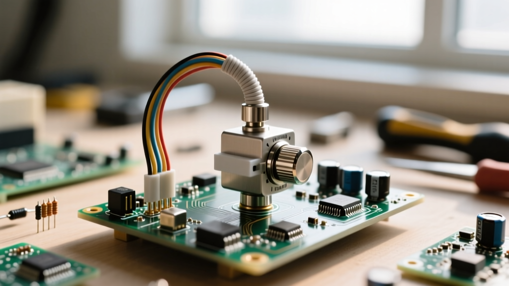
Connecting an automotive potentiometer to an automotive-grade ADC requires more than just wiring the wiper to a GPIO pin. The electrical noise floor of a vehicle is notoriously hostile.
The Ratiometric Imperative
Engineering Pro-Tip: Never use a fixed, high-precision voltage reference (like a 4.096V shunt reference) for an automotive potentiometer ADC. Always use a ratiometric configuration where the ADC VREF is tied to the exact same 5V regulator powering the potentiometer track. If the 5V rail sags to 4.8V due to alternator ripple or starter-motor cranking, the ADC reading remains mathematically identical because both the excitation voltage and the reference voltage dropped by the exact same percentage.
Hardware Filtering for Wiper Noise
Conductive plastic is smooth, but it is not perfect. To prevent high-frequency wiper noise from aliasing into your microcontroller's ADC, implement a simple hardware RC low-pass filter. A 100Ω series resistor combined with a 100nF X7R ceramic capacitor placed physically adjacent to the MCU pin creates a cutoff frequency of roughly 15.9 kHz. This filters out micro-second wiper bounces without introducing the phase lag that would delay critical throttle-response calculations.
Sourcing and Prototyping Considerations
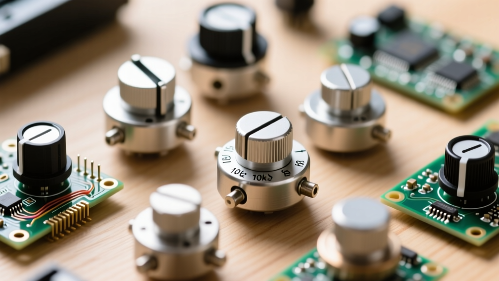
When prototyping an automotive subsystem, avoid the temptation to use off-the-shelf hobbyist potentiometers (like the ubiquitous Bourns 3386P cermet trimmers) for dynamic testing. While they cost under $1.00, their 200-cycle mechanical life will degrade before your first design review.
For prototyping, source single-turn or multi-turn conductive plastic precision pots (such as the Vishay 533 series or Bourns 3540 series). Expect to pay between $8.00 and $18.00 per unit in low quantities. While this is a steep premium over standard carbon pots, the data you gather regarding linearity, hysteresis, and CRV will accurately reflect the behavior of the high-volume, custom-molded sensors your Tier-1 supplier will eventually manufacture for the production vehicle.