
Welcome to the Alternating Current Wiki: Beyond the Basics
Most electrical textbooks treat Alternating Current (AC) as a perfect, unchanging sine wave. In the real world of DIY electronics, residential wiring, and industrial microcontroller deployments, AC power is messy, distorted, and prone to complex fault conditions. Welcome to the ElectricalFlux alternating current wiki, a specialized troubleshooting database designed for makers, electricians, and engineers who need to diagnose real-world AC anomalies. Unlike a standard theoretical guide, this wiki focuses entirely on practical diagnostics, advanced wire sizing considerations for AC impedance, and the exact failure modes that cause breakers to trip or components to fry.
Whether you are debugging a noisy power supply for an Arduino-based smart home hub or troubleshooting a 240V split-phase compressor circuit, understanding the true nature of AC waveforms is critical. For a foundational refresher on AC theory, the All About Circuits AC textbook remains an excellent baseline. However, this guide will push past theory into the gritty reality of diagnostics.
Decoding AC Waveform Anomalies and Harmonics
The most common mistake DIYers make when troubleshooting AC power is assuming a standard digital multimeter is telling them the whole truth. Standard meters assume a pure 60Hz (or 50Hz) sine wave. When you introduce non-linear loads—such as variable frequency drives (VFDs), LED drivers, or switching power supplies—the waveform becomes distorted. This introduces harmonics, which are integer multiples of the fundamental frequency.
High Total Harmonic Distortion (THD) causes excessive heat in neutral conductors and transformer cores. If your workshop's 20A breaker keeps tripping but your clamp meter only reads 14A, you are likely dealing with harmonic currents. According to Fluke's guide on Total Harmonic Distortion, triplen harmonics (3rd, 9th, 15th) do not cancel out in the neutral; they add together. This means a shared neutral conductor can actually carry more current than the phase conductors, leading to silent, catastrophic thermal failures inside your walls.
Essential Diagnostic Tools for AC Faults
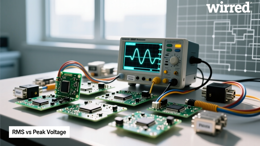
To properly troubleshoot AC systems, you must upgrade your diagnostic toolkit. Relying on an average-responding multimeter will yield wildly inaccurate readings when measuring the output of a modified sine wave inverter or a dimmer switch circuit.
True-RMS vs. Average-Responding vs. Oscilloscopes
| Tool Category | Example Model | Approx. Price | Best Use Case | Limitations |
|---|---|---|---|---|
| Average-Responding DMM | Klein Tools MM400 | $50 | Basic continuity, pure sine wave voltage checks | Fails on non-linear loads; reads up to 40% low on distorted waves |
| True-RMS Industrial DMM | Fluke 87V | $450 | Accurate AC voltage/current on VFDs, LED drivers, and inverters | Cannot visualize waveform shape or high-frequency noise |
| Handheld Oscilloscope | OWON VDS1022I | $120 | Visualizing zero-crossing distortion, ringing, and high-frequency noise | Requires isolation transformers or differential probes for safe mains use |
As noted in Fluke's True-RMS measurement guide, a True-RMS meter calculates the effective heating value of the AC waveform, which is the only accurate way to size wires and verify breaker loads in modern environments filled with switching electronics.
Step-by-Step Troubleshooting: The Floating Neutral Catastrophe
One of the most dangerous and frequently misunderstood AC faults in North American split-phase (120V/240V) systems is the floating neutral. This occurs in Multi-Wire Branch Circuits (MWBC) or at the main service panel when the neutral connection becomes loose or corroded.
The Scenario: You have an MWBC sharing a single neutral wire. Phase A (black) powers a 10W LED lamp. Phase B (red) powers an 1800W space heater. The shared neutral wire breaks at the panel.
The Physics: Without the neutral to return current to the transformer, Phase A and Phase B become a series circuit across the full 240V potential. Because the space heater has very low resistance and the LED lamp has very high resistance, Ohm's Law dictates that the voltage will divide unevenly. The space heater will receive roughly 5V (and fail to turn on), while the LED lamp will be subjected to 235V. The LED driver will violently explode, potentially starting a fire.
Troubleshooting Steps:
- Measure the voltage from Phase A to Neutral, and Phase B to Neutral. If one reads 145V and the other reads 95V, you have a floating neutral.
- Immediately shut off the main breaker. Do not touch the neutral bus bar, as it may be energized at 120V relative to ground.
- Inspect the neutral pigtail connections at the panel and the first receptacle in the daisy chain for loose torque or back-stabbed push-in connectors, which are notorious for failing under thermal cycling.
Advanced Wire Sizing: AC Impedance and the Skin Effect
When sizing conductors for AC power, DIYers often rely on standard DC voltage drop calculators. This is a critical error for large-gauge wiring. In AC systems, the current tends to flow on the outer surface of the conductor—a phenomenon known as the skin effect.
For standard DIY wire sizes (14 AWG to 2 AWG), the skin effect at 60Hz is negligible. However, if you are sizing service entrance conductors like 250 kcmil or 400 kcmil for a 200A to 400A residential subpanel, the AC resistance (Rac) can be 10% to 15% higher than the DC resistance (Rdc). Furthermore, AC circuits possess inductive reactance (Xl), meaning you must calculate using AC Impedance (Z), not just resistance.
Expert Tip: When calculating voltage drop for large AC feeders, always use the 'Z' (effective impedance) values from NEC Chapter 9, Table 9, rather than simple DC resistance formulas. Failing to account for AC impedance and power factor will result in undersized wires, excessive thermal buildup, and premature degradation of XHHW-2 insulation.
Frequently Diagnosed AC Failure Modes (Quick Reference)
Use this quick-reference matrix to isolate common AC faults in DIY and prototyping environments:
- Symptom: Microcontroller resets randomly when a relay clicks.
Root Cause: Inductive kickback and AC zero-crossing noise coupling into the DC logic rail.
Fix: Implement an RC snubber network across the AC relay coil and use opto-isolators for the trigger signal. - Symptom: Dimmer switch buzzes loudly and feels hot.
Root Cause: Using a standard TRIAC dimmer with incompatible LED drivers that lack dummy load resistors.
Fix: Upgrade to an ELV (Electronic Low Voltage) dimmer or install an Lutron LUT-MLC dummy load capacitor in parallel with the LED fixture. - Symptom: 240V compressor motor hums but won't spin, trips breaker after 5 seconds.
Root Cause: Failed run capacitor or seized start winding, causing extreme Locked Rotor Amps (LRA).
Fix: Test the dual-run capacitor with a multimeter's capacitance setting. Replace if microfarad reading is more than 5% below the rated spec.
Final Thoughts on AC Safety and Diagnostics
Troubleshooting alternating current requires a deep respect for the invisible forces at play. Always verify your meter's CAT rating before probing mains voltage; a CAT II meter will violently explode if used to measure a 240V service panel fault. By understanding waveform distortion, the dangers of floating neutrals, and the nuances of AC impedance in wire sizing, you can elevate your DIY electrical projects from amateur experiments to professional-grade installations. Keep this alternating current wiki bookmarked as your primary reference for diagnosing the complex, non-linear realities of modern AC power systems.