
The Anatomy of an Alternating Current Cycle
When electricians and engineers size conductors for residential, commercial, or industrial systems, the primary focus is often on ampacity and voltage drop. However, the underlying physics of the alternating current cycle introduces complex variables that direct current (DC) systems simply do not possess. Unlike DC, where electrons flow in a single, continuous direction, alternating current (AC) periodically reverses direction, creating a sinusoidal waveform that fundamentally alters how electrical energy interacts with copper and aluminum conductors.
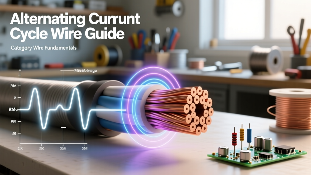
A standard North American 60Hz AC power supply completes 60 full cycles every second. This means a single alternating current cycle lasts exactly 16.67 milliseconds. Within this brief window, the voltage and current rise from zero to a positive peak, fall back through zero to a negative peak, and return to zero again. Understanding the precise mechanics of this cycle is not just an academic exercise; it directly dictates insulation requirements, thermal management, and the effective cross-sectional area of the wire you select for your project.
Sine Wave Mechanics: Zero-Crossing and Arc Suppression
Every alternating current cycle features two 'zero-crossing' points where the voltage and current momentarily drop to absolute zero. This physical characteristic is the reason AC circuit breakers can successfully interrupt massive fault currents. When a breaker trips, the ensuing electrical arc is naturally extinguished at the next zero-crossing point of the cycle. However, in high-inductance circuits, the current waveform can lag behind the voltage waveform, altering the exact moment of zero-current and placing immense stress on breaker contacts and the upstream wiring busbars.
RMS vs. Peak Voltage: The Insulation Factor
One of the most common misconceptions in electrical wiring is assuming that a '120V' or '480V' system operates strictly at those voltages. In reality, these numbers represent the Root Mean Square (RMS) voltage, which is the effective heating value of the AC waveform compared to an equivalent DC source. The actual voltage during the peak of the alternating current cycle is significantly higher.
To find the peak voltage, you multiply the RMS voltage by the square root of 2 (approximately 1.414). Therefore, a standard 120V RMS circuit actually peaks at roughly 170V during every cycle. For wire sizing, the ampacity determines the conductor's thickness (gauge), but the peak voltage determines the required insulation thickness and dielectric strength.
Reference Chart: Standard AC Voltages and Peak Insulation Stress
| Nominal RMS Voltage | Peak Voltage (V) | Peak-to-Peak Voltage (V) | Standard Wire Insulation Rating | Dielectric Safety Margin |
|---|---|---|---|---|
| 120V AC | 169.7V | 339.4V | 600V (THHN/THWN-2) | High (253%) |
| 208V AC | 294.1V | 588.2V | 600V (THHN/THWN-2) | Moderate (104%) |
| 240V AC | 339.4V | 678.8V | 600V (THHN/THWN-2) | Moderate (76%) |
| 480V AC | 678.8V | 1357.6V | 600V (THHN/THWN-2) | CRITICAL: Exceeds 600V Rating |
| 480V AC | 678.8V | 1357.6V | 1000V (XHHW-2) | High (47%) |
Expert Insight: While 600V-rated THHN wire is ubiquitous in 480V industrial panels, the peak of the alternating current cycle actually reaches 678.8V. During transient voltage spikes or switching surges, this peak can easily exceed the dielectric breakdown threshold of 600V insulation. For mission-critical 480V feeders, specifying 1000V-rated XHHW-2 insulation provides a necessary buffer against cycle-peak degradation over time.
Frequency, Hertz, and the Skin Effect in AC Wiring
The frequency of the alternating current cycle dictates how deeply electrons penetrate the conductor. In a DC circuit, current density is uniform across the entire cross-section of the wire. In an AC circuit, the rapidly reversing magnetic fields generated by the alternating current cycle induce eddy currents within the conductor itself. These eddy currents cancel out the flow of electrons in the center of the wire and reinforce the flow at the outer edges.
This phenomenon is known as the skin effect. As frequency increases, the effective 'skin depth'—the outer layer of the conductor where 98% of the current flows—becomes thinner. According to data published by Georgia State University's HyperPhysics database, the skin depth in copper at a standard 60Hz is approximately 8.47 millimeters. At 60Hz, the skin effect is negligible for wires smaller than 500 kcmil. However, in specialized applications like aerospace (400Hz) or high-frequency industrial drives, the skin depth shrinks dramatically, rendering the center of a thick conductor completely useless for current transfer.
Calculating Skin Depth by Frequency and Material
| System Frequency | Copper Skin Depth (mm) | Aluminum Skin Depth (mm) | Wire Sizing Implication |
|---|---|---|---|
| 50Hz (European Grid) | 9.28 mm | 11.6 mm | Standard NEC/IEC ampacity tables apply up to 500 kcmil. |
| 60Hz (North American Grid) | 8.47 mm | 10.6 mm | Standard ampacity tables apply; large busbars may require hollow cores. |
| 400Hz (Aerospace/Military) | 3.28 mm | 4.11 mm | Must use multiple parallel smaller conductors; large single wires overheat. |
| 1,000Hz (VFD Switching) | 2.08 mm | 2.60 mm | Severe skin effect; requires specialized symmetrical shielded cables. |
When sizing large feeders (e.g., 750 kcmil or 1000 kcmil) for standard 60Hz mains, the skin effect begins to introduce a measurable increase in AC resistance compared to DC resistance. To mitigate this, engineers often parallel multiple smaller conductors (e.g., three sets of 350 kcmil) rather than using a single massive 1000 kcmil cable. This increases the total surface area available for the alternating current cycle to travel across, reducing heat buildup and voltage drop.
Harmonic Distortion: When the Cycle Loses its Shape
The ideal alternating current cycle is a perfect sine wave. However, modern electrical environments are saturated with non-linear loads such as Variable Frequency Drives (VFDs), LED lighting ballasts, and switched-mode power supplies. These devices draw current in abrupt pulses rather than a smooth sinusoidal curve, severely distorting the waveform.
This distortion introduces harmonics—frequencies that are integer multiples of the fundamental 60Hz cycle. The 3rd harmonic (180Hz) and the 5th harmonic (300Hz) are particularly prevalent. Because skin effect scales with the square root of frequency, these higher-order harmonics experience immense resistance, generating excessive heat in the conductors. Furthermore, triplen harmonics (3rd, 9th, 15th) do not cancel out on the neutral wire in a three-phase wye system; they stack arithmetically.
According to power quality research from Fluke regarding True-RMS measurements, standard averaging multimeters will completely miss the thermal impact of these distorted cycles, leading technicians to believe a circuit is safe when it is actually overheating. To address this in wire sizing:
- Upsize the Neutral: In commercial buildings with heavy IT infrastructure or LED arrays, size the neutral conductor at 125% to 150% of the phase conductors to handle triplen harmonic stacking.
- Derate for Heat: Apply NEC Article 310.15 derating factors aggressively, as the distorted alternating current cycle generates more I²R heat than a pure sine wave of the same RMS amperage.
- Use K-Rated Transformers: Ensure downstream distribution transformers are K-factor rated (e.g., K-13 or K-20) to handle the localized eddy current losses caused by high-frequency harmonics.
Stranded vs. Solid Conductors in AC Applications
A frequent question among DIYers and junior engineers is whether stranded wire mitigates the skin effect of the alternating current cycle. The short answer is: not at standard power frequencies.
At 60Hz, the electromagnetic coupling between the individual strands in a standard stranded conductor is so tight that the entire bundle acts as a single solid mass. The eddy currents still form across the outer boundary of the entire cable bundle. Therefore, a 4 AWG stranded wire and a 4 AWG solid wire will exhibit virtually identical AC resistance and skin effect characteristics at 60Hz. Stranded wire is chosen for mains wiring purely for mechanical flexibility and ease of pulling through conduit bends.
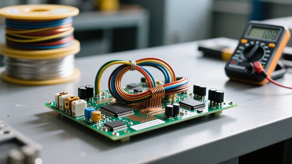
To genuinely defeat the skin effect at higher frequencies, you must use Litz wire. Litz wire consists of individually insulated micro-strands that are woven or braided in a specific geometric pattern. This weaving forces the current to constantly transpose from the center of the bundle to the outside, ensuring every strand spends equal time on the 'skin' of the conductor. While Litz wire is standard in high-frequency transformers and induction heating coils, it is entirely unnecessary and cost-prohibitive for standard 50/60Hz building wiring.
Summary Checklist for AC Wire Sizing
When designing or modifying an AC electrical system, look beyond basic ampacity charts and consider the physical realities of the alternating current cycle:
- Verify Peak Voltage: Ensure your wire's insulation rating (e.g., 600V) safely exceeds the peak-to-ground voltage of the system, especially on 480V ungrounded or corner-grounded delta systems.
- Account for Skin Effect on Large Feeders: For conductors larger than 500 kcmil at 60Hz, consider paralleling smaller wires to maximize surface area and reduce AC resistance.
- Anticipate Harmonics: If the load profile includes heavy VFDs or data centers, upsize the neutral conductor and specify True-RMS measurement tools for commissioning.
- Match Frequency to Material: If working on 400Hz aerospace or marine systems, drastically adjust your skin-depth calculations and avoid large-gauge solid conductors entirely.
By respecting the physics of the alternating current cycle, you ensure that your wiring systems are not only code-compliant but thermally optimized for decades of reliable operation.