
The 45 Amp Dilemma: Standard vs. Continuous Loads
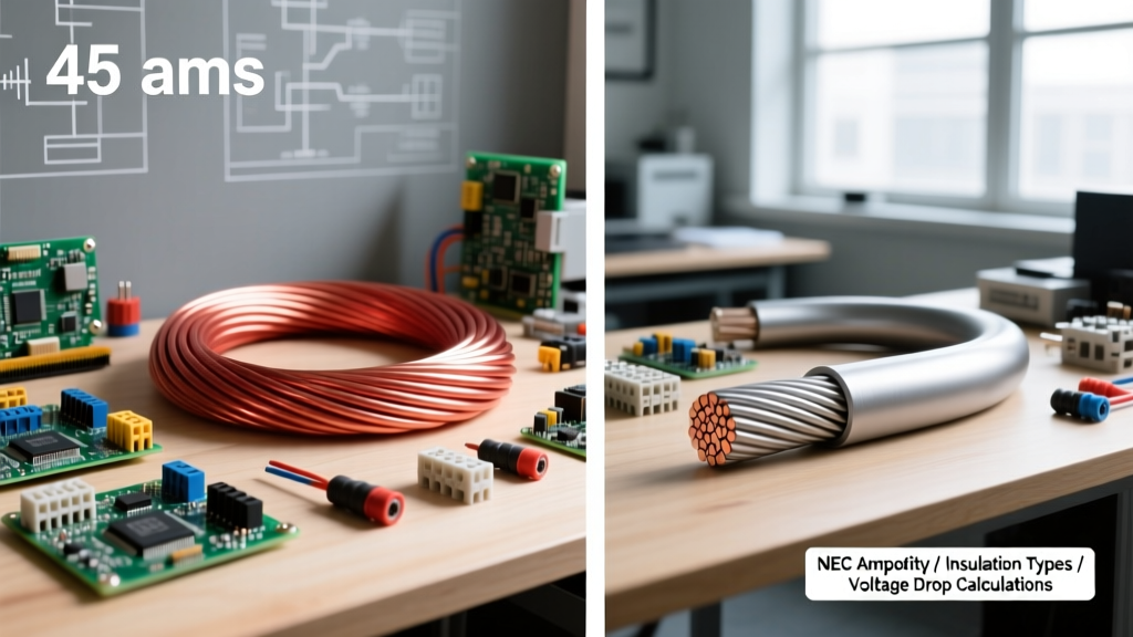
When sizing wire for a 45 amp circuit, electricians and advanced DIYers often hit a technical wall. Unlike the ubiquitous 20A, 30A, or 50A circuits, a 45 amp breaker is a highly specific standard size listed in NEC Article 240.6(A). You typically encounter a 45 amp wire size requirement in three distinct scenarios: specific HVAC condenser units, heavy-duty welding receptacles, or continuous loads (like a 36-amp EV charger) that require a 125% safety multiplier (36A x 1.25 = 45A).
Choosing the correct 45 amp wire size is not a simple one-size-fits-all answer. It requires a deep comparison of conductor materials, insulation types, voltage drop over distance, and termination temperature limits. In this comprehensive comparison guide, we break down the exact physics and National Electrical Code (NEC) requirements to ensure your 45A circuit is safe, efficient, and fully code-compliant.
The Continuous vs. Non-Continuous Load Factor
Before comparing copper and aluminum, we must define the nature of your 45A load. The NEC defines a continuous load as any load where the maximum current is expected to continue for three hours or more. This distinction fundamentally changes the wire gauge you must pull:
- Non-Continuous 45A Load (e.g., Welder, Intermittent Machinery): You size the wire based strictly on the 45A requirement. The wire must have an allowable ampacity of at least 45 amps.
- Continuous 45A Load (e.g., EV Charger, Industrial Heater): NEC Article 210.20(A) mandates that the conductors must be sized at 125% of the continuous load. Therefore, a 45A continuous load requires a wire with an ampacity of at least 56.25 amps (45 x 1.25). This pushes you into a completely different wire gauge category.
Material Showdown: Copper vs. Aluminum for 45A Circuits
The choice between copper and aluminum dictates not only your material cost but also your conduit fill capacity and termination methods. Below is a direct comparison of the wire gauges required for 45 amp circuits based on the Southwire Ampacity Tables and NEC Table 310.15(B)(16).
| Material | Wire Gauge (AWG) | 75°C Ampacity | 90°C Ampacity | Best Application |
|---|---|---|---|---|
| Copper | 8 AWG | 50A | 55A | Standard indoor 45A non-continuous loads. |
| Copper | 6 AWG | 65A | 75A | 45A continuous loads (requires 56.25A capacity). |
| Aluminum | 6 AWG | 50A | 55A | Budget-friendly non-continuous 45A loads. |
| Aluminum | 4 AWG | 65A | 75A | Continuous 45A loads or long-distance runs. |
The Verdict: For a standard 45A non-continuous breaker, 8 AWG Copper or 6 AWG Aluminum is sufficient. However, if your 45A load is continuous, you must step up to 6 AWG Copper or 4 AWG Aluminum. Always remember that aluminum requires larger conduit diameters and specific anti-oxidant pastes at termination points to prevent galvanic corrosion and thermal creep.
Insulation Profiles: THHN vs. XHHW-2
Once you have selected your gauge and material, the insulation jacket becomes the next critical variable. The two most common building wires are THHN and XHHW-2, and they behave very differently in a 45A circuit.
Conduit Fill and Wet Location Ratings
THHN (Thermoplastic High Heat-resistant Nylon-coated): THHN features a very thin nylon outer jacket. This allows for more wires to be pulled through a single conduit (better conduit fill). However, the nylon jacket is notoriously slippery, which can make it difficult to grip in certain lug terminations, and it is highly susceptible to degradation if exposed to water or certain chemical solvents inside wet conduit runs.
XHHW-2 (Cross-Linked Polyethylene): XHHW-2 lacks the nylon jacket, making the insulation slightly thicker. While this marginally reduces conduit fill capacity, the cross-linked polyethylene is vastly superior for wet locations, high-temperature resilience, and physical abrasion resistance. For outdoor 45A subpanels or underground conduit sweeps where moisture accumulation is inevitable, XHHW-2 is the undisputed champion.
Voltage Drop: The Hidden 45A Circuit Killer
Ampacity tables only tell half the story. If your 45A circuit runs a significant distance from the main panel, voltage drop will cause equipment failure, motor burnout, and excessive heat generation. The NEC recommends keeping voltage drop under 3% for branch circuits and 5% overall.
Let us calculate the voltage drop for a 45A load on 8 AWG Copper running 150 feet on a 240V circuit. Using the standard single-phase voltage drop formula: VD = (2 x K x I x D) / CM.
- K (Copper Resistivity) = 12.9 ohms-cmil/ft
- I (Current) = 45 Amps
- D (Distance) = 150 ft
- CM (Circular Mils for 8 AWG) = 16,510
VD = (2 x 12.9 x 45 x 150) / 16,510 = 10.54 Volts.
On a 240V circuit, a 10.54V drop represents a 4.39% drop. While this is under the 5% total NEC threshold, it exceeds the 3% recommendation for a single branch circuit. If this were a 120V circuit, the drop would be a catastrophic 8.78%. Solution: For any 45A run exceeding 100 feet, bypass 8 AWG entirely and pull 6 AWG Copper to maintain optimal voltage regulation and system efficiency.
Expert Insight: Never rely solely on the breaker to protect against voltage drop. A 45A breaker will happily hold a 44A load even if the voltage at the appliance has dropped to 210V, causing the appliance's internal components to overheat and fail prematurely while the wire insulation slowly degrades from the inside out.
The Termination Temperature Trap (NEC 110.14)
One of the most common failure modes in DIY and even journeyman-level electrical work is misinterpreting the 90°C column in the NEC ampacity tables. Both 8 AWG THHN and 6 AWG XHHW-2 are rated for 90°C. However, NEC Article 110.14(C) strictly governs termination limits.
Almost all standard circuit breakers and disconnect switches rated 100A or less are tested and listed for 75°C terminations. This means that even if your wire is rated for 90°C, the final allowable ampacity of the circuit is bottlenecked by the 75°C rating of the breaker lug. You may only use the 90°C column for ambient temperature derating (e.g., if the wire runs through a 110°F attic space), but the base ampacity must be anchored to the 75°C column. This is why 8 AWG copper is capped at 50A for termination purposes, safely covering your 45A non-continuous requirement, but leaving no room for continuous load manipulation.
Real-World Failure Modes to Avoid
- Aluminum Creep: If using 6 AWG or 4 AWG aluminum for your 45A circuit, you must use a calibrated torque screwdriver to tighten the lugs to the manufacturer's exact inch-pound specification. Aluminum expands and contracts at a different rate than brass lugs; under-torquing leads to arcing and panel fires.
- Shared Neutral Overload: In multi-wire branch circuits (MWBC), if you are running two 45A 120V circuits on different phases sharing a single neutral, the neutral wire must be sized to handle the maximum unbalanced current, which in worst-case harmonic scenarios can exceed the phase conductors.
- Conduit Derating: If you pull more than three current-carrying 45A conductors in a single raceway, NEC Table 310.15(B)(3)(a) requires you to derate the ampacity. Four to six conductors require an 80% derating factor, which instantly drops 8 AWG copper (55A at 90°C) down to 44A—making it illegal for a 45A circuit. You must step up to 6 AWG in shared conduits.
By understanding the interplay between continuous load mathematics, material physics, and strict NEC termination rules, you can confidently design a 45 amp circuit that will operate safely and reliably for decades.