
Demystifying the 1 Microfarad Capacitor Code
When sourcing components for your next PCB layout or breadboard prototype, understanding the 1 microfarad capacitor code is an essential skill. Unlike resistors, which use a straightforward color band system, capacitors employ a fragmented mix of direct printing, 3-digit EIA codes, and surface-mount silkscreens. The 1µF (microfarad) capacitor is arguably the most common workhorse in modern electronics, serving as the primary decoupling capacitor for IC power rails and a critical timing element in analog filters.
However, if you order a '1 microfarad capacitor' without specifying the dielectric, voltage, or package, you will end up with a randomized assortment of parts that may fail in your specific application. This guide decodes the 105 capacitor code, explores the hidden dangers of DC bias derating, and provides a rigorous buying framework for electrical engineers and DIYers alike.
The EIA 3-Digit Math: Why 1µF is Written as '105'
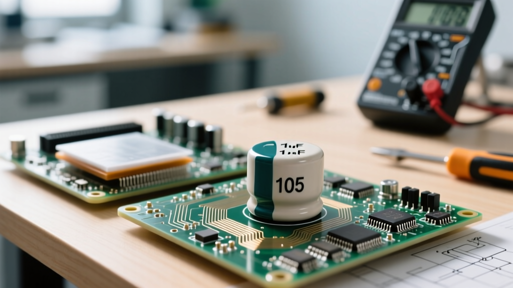
For ceramic and film capacitors, manufacturers rely on the standard EIA (Electronic Industries Alliance) 3-digit code. The code is read in picofarads (pF). Here is the exact breakdown of the 105 capacitor code:
- First Digit (1): The first significant figure.
- Second Digit (0): The second significant figure.
- Third Digit (5): The multiplier (number of zeros to add).
Therefore, 10 followed by five zeros equals 1,000,000 pF. To convert this to microfarads, we divide by 1,000,000. Thus, 1,000,000 pF = 1,000 nF = 1 µF. You will frequently see this printed as 105K or 105J on through-hole polyester film caps or DIP ceramics. The trailing letter denotes the tolerance: J means ±5%, K means ±10%, and M means ±20%. For a comprehensive lookup, the DigiKey Capacitor Code Calculator is an excellent bookmark for quick bench-side conversions.
Dielectric Showdown: Which 1µF Type Do You Actually Need?
Decoding the '105' is only the first step. The physical construction of the capacitor dictates its Equivalent Series Resistance (ESR), leakage current, and high-frequency behavior. Below is a selection matrix to help you choose the right 1µF chemistry for your schematic.
| Dielectric / Type | Typical Code | Polarity | ESR Range | Best Application |
|---|---|---|---|---|
| MLCC (X7R Ceramic) | 105K | No | 10mΩ - 50mΩ | High-frequency IC decoupling, RF filtering |
| Aluminum Electrolytic | 1µF 50V | Yes | 5Ω - 20Ω | Low-freq audio coupling, bulk power storage |
| Tantalum | 106K (10µF) / 105K | Yes | 1Ω - 5Ω | Space-constrained medical/aerospace (with derating) |
| Polyester Film (Mylar) | 105J | No | High | Audio crossovers, high-voltage analog timing |
Pro-Tip: Never use standard aluminum electrolytics for high-speed digital decoupling (like bypassing an STM32 or FPGA). Their high ESR and parasitic inductance make them useless above a few hundred kilohertz. Stick to MLCC (Multi-Layer Ceramic Capacitors) for digital power rails.
The Hidden Trap: DC Bias and Capacitance Loss
The most critical mistake junior engineers make when buying 1µF MLCCs is ignoring DC bias derating. Ceramic capacitors (specifically Class II dielectrics like X5R and X7R) exhibit a piezoelectric effect where their physical capacitance drops dramatically as DC voltage is applied across their terminals.
Engineering Reality Check: A standard 0805 package, 1µF, X5R, 16V ceramic capacitor might measure exactly 1.0µF on your benchtop multimeter at 0V. However, if you place it on a 12V power rail, its actual capacitance under operating conditions can plummet to 0.2µF—an 80% loss! This can cause catastrophic instability in switching regulators and LDOs that require a specific minimum output capacitance for loop stability.
To combat this, you must use tools like the Murata SimSurfing Tool before finalizing your BOM. If your circuit operates at 12V, do not buy a 16V rated 1µF cap. Instead, buy a 50V rated 1µF cap (like the Murata GRM21BR71H105KA88L) or step up to a larger 1206 package. The thicker dielectric layers in higher-voltage and larger-package capacitors resist the DC bias squeezing effect far better.
Temperature Coefficients: X7R vs. Y5V vs. C0G
When browsing distributor catalogs, you will see letters appended to the voltage and capacitance codes. These dictate the EIA temperature characteristic.
- C0G / NP0 (Class I): Near-zero temperature drift. Highly stable. Unfortunately, 1µF is virtually impossible to find in C0G without resorting to massive, expensive through-hole or specialty SMD packages. Use C0G for pF and low-nF ranges only.
- X7R (Class II): The gold standard for 1µF decoupling. It guarantees ±15% capacitance variation from -55°C to +125°C. Always default to X7R for industrial and automotive prototypes.
- X5R (Class II): Similar to X7R but rated only to +85°C. Acceptable for consumer USB-powered gadgets, but avoid in automotive or outdoor enclosures.
- Y5V (Class III): Avoid at all costs. Y5V capacitors are cheap to manufacture but can lose up to 80% of their capacitance simply by reaching room temperature extremes. A 105 Y5V capacitor is a liability in any serious design.
Sourcing Authentic 105 Capacitors: Avoiding the Counterfeit Market
As we navigate the component supply chain in 2026, the market remains flooded with counterfeit MLCCs. Fake capacitors often fail in three ways: they exhibit massive microphonic noise (acting like microphones picking up board vibrations), they suffer from internal delamination causing short circuits, or they simply possess a fraction of the advertised 1µF capacity.
Where to Buy for Prototyping vs. Production
For hobbyists and rapid prototyping, the convenience of Amazon or AliExpress assortments is tempting. However, those $5 '1000-piece capacitor kits' are almost guaranteed to contain out-of-spec Y5V or degraded X5R dies. When your 555 timer circuit or buck converter fails inexplicably, the capacitor is usually the culprit.
- Tier 1 (Production & Critical Prototypes): DigiKey, Mouser, Farnell, LCSC (Direct). These authorized distributors pull directly from reels manufactured by Murata, TDK, Samsung, and Taiyo Yuden.
- Tier 2 (Hobbyist Convenience): SparkFun, Adafruit, or specialized Amazon storefronts that explicitly list their supply chain. Avoid unbranded 'white label' kits.
When ordering from a Tier 1 distributor, search using the parameter filters: Capacitance: 1µF | Dielectric: X7R | Voltage: 25V or 50V | Package: 0805. This ensures you receive a component that will behave predictably under both thermal and electrical stress, honoring the true intent of the 105 code.
Final Prototyping Recommendations
If you are hand-soldering 1µF components for a breadboard or perfboard, buy leaded (through-hole) X7R radial ceramics or high-quality Panasonic film capacitors. If you are designing a custom PCB, standardize your BOM on 0805 or 1206 X7R MLCCs rated for at least 2.5x your maximum rail voltage to eliminate DC bias derating headaches. Master the code, respect the dielectric, and your power delivery networks will remain rock-solid.