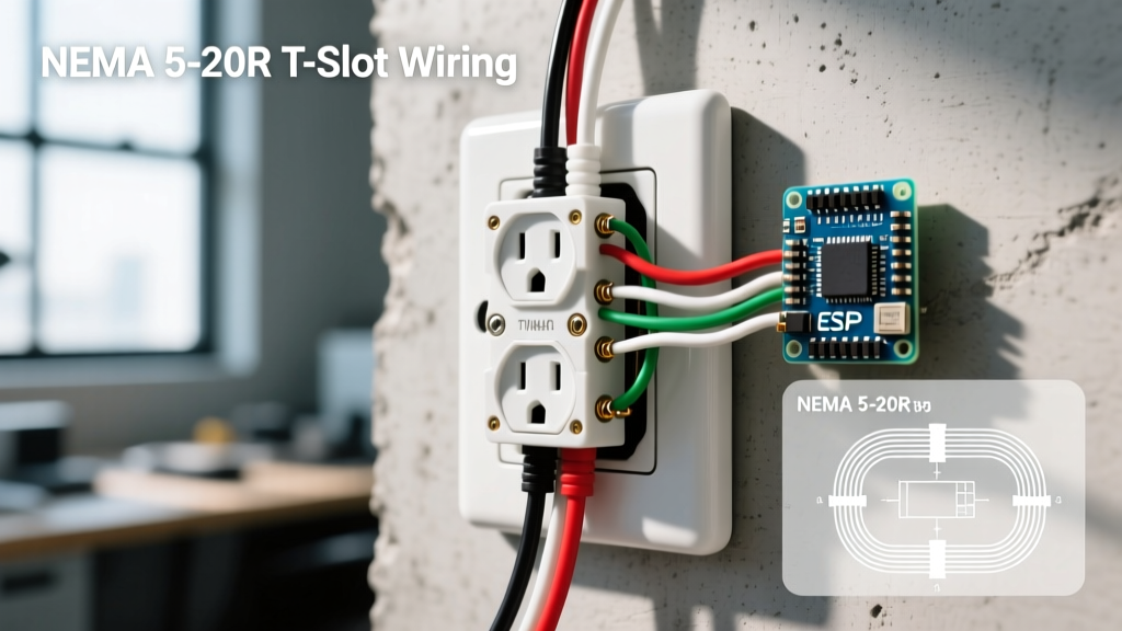
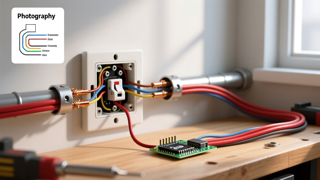
If you are wiring a double switch light setup for standard 15A/120V residential circuits, a standard dual-gang wall switch is adequate. However, if you are switching 240V lighting arrays, high-bay commercial fixtures, or massive LED banks with high inrush currents, a standard wall switch will quickly pit, overheat, and weld its contacts shut. For loads exceeding 15A, 277V, or exhibiting high inrush, you must step up to a heavy-duty Double-Pole Single-Throw (DPST) toggle switch (like the Leviton 3032) or a dedicated electromechanical lighting contactor (like the Eaton C4021).
The direct answer for high-load applications: use a lighting contactor controlled by a low-current pilot switch. This keeps the heavy 240V/277V arcing contained inside a robust contactor while allowing you to use standard low-voltage smart switches or standard toggles on the control side. Below is the exact specification breakdown, wiring methodology, and diagnostic path for these electromechanical components.
Component Specifications: DPST Switches vs. Lighting Contactors
When selecting a double-pole switching device, you must look beyond the basic amperage rating. The breaking capacity and inrush tolerance dictate whether the switch will survive the first millisecond of turning on a modern LED driver or a magnetic ballast. The table below compares common devices used in double switch light circuits.
| Device Type | Coil / Pilot Voltage | Contact Rating (Resistive) | Breaking Capacity | Inrush Tolerance |
|---|---|---|---|---|
| Standard Dual-Gang Wall Switch | N/A (Manual) | 15A @ 120V AC | ~50A | Low (Fails on SMPS loads) |
| Heavy-Duty DPST Toggle (Leviton 3032) | N/A (Manual) | 30A @ 120/277V AC | ~150A | Moderate (Good for HID/Incandescent) |
| 2-Pole Lighting Contactor (Eaton C4021) | 120V AC (A1/A2) | 30A @ 277V AC | 300A | High (100A+ peak inrush) |
| 3-Pole Contactor (Square D 8903L) | 24V AC/DC (A1/A2) | 30A @ 600V AC | 400A | Very High (Industrial arrays) |
Worked Numeric Example: Consider a 1000W LED high-bay light running on a 240V circuit. The nominal steady-state current is roughly 4.2A (1000W / 240V). However, the internal Switch-Mode Power Supply (SMPS) capacitors draw 10x to 20x inrush current for the first AC half-cycle to charge. That equates to a 40A to 80A peak inrush spike. A standard 15A wall switch will arc heavily and degrade within weeks. A contactor rated for 100A inrush will close cleanly, absorbing the mechanical and electrical stress without pitting the silver-alloy contacts.
Coil vs. Contact Wiring and DC Flyback Protection
Electromechanical contactors physically separate the control circuit from the load circuit. Understanding this division is critical for safe wiring.
The Contact Side (Load Circuit)
The contact side handles the heavy lifting. Line voltage (L1, L2) enters the top terminals, and the load (T1, T2) exits the bottom. When wiring a double switch light setup for 240V (like a grow light or baseboard heater with an integrated light), both ungrounded conductors (hot wires) must pass through the contactor poles simultaneously. This ensures complete circuit isolation when open. Never switch only one leg of a 240V circuit; it leaves the fixture energized and poses a lethal shock hazard during maintenance.
The Coil Side (Control Circuit)
The coil terminals (typically labeled A1 and A2) receive the low-current signal that energizes the electromagnet, pulling the heavy contacts closed. This allows you to run 18 AWG or 16 AWG control wire from a smart home hub, a photocell, or a standard 15A single-pole toggle switch to the contactor coil.
Selection Decision Path by Lighting Load Type
Datasheets list multiple rating columns (Resistive, Inductive, Tungsten, Motor, FLA/LRA). The most common mistake DIYers make is sizing the switch based on the resistive column when the load is actually inductive or electronic. Use the decision tree below to determine which rating column governs your specific lighting load.
| Lighting Load Type | Governing Rating Column | Why It Governs | Example Scenario |
|---|---|---|---|
| Incandescent / Halogen | Tungsten / Inrush | Cold filament resistance is 1/15th of hot resistance, causing massive initial current surge. | Vintage theater lighting, heat lamps. |
| Modern LED Arrays (SMPS) | Electronic / Inrush (Capacitive) | Charging internal DC bus capacitors causes microsecond current spikes up to 20x nominal. | Commercial high-bay LEDs, stadium floods. |
| HID with Magnetic Ballast | Inductive / Ballast | Highly inductive coils resist current changes, creating severe arcing upon contact opening. | Older streetlights, metal halide warehouse lights. |
| Motorized Louvers / Track | Motor (FLA / LRA) | Locked Rotor Amps (LRA) dictate the starting surge; inductive kickback dictates breaking capacity. | Motorized stage lighting rigs, automated skylights. |
If your contactor or DPST switch datasheet does not explicitly list a rating for your specific load type (e.g., it only lists "Resistive Amps"), you must apply a derating factor. A standard rule of thumb in NFPA 70 (NEC) Article 410 and general electromechanical design is to derate resistive contacts by 50% to 75% when switching inductive or high-inrush electronic loads.
Testing, Diagnostics, and Replacement Criteria
Electromechanical switches and contactors are wear items. Every time contacts open under load, a micro-arc vaporizes a tiny amount of the silver-alloy contact material. Over thousands of cycles, this leads to pitting, increased resistance, and eventual failure. Here is how to test and evaluate them.
How to Test Dead (De-Energized)
- Isolate and Verify: Turn off the breaker and verify the circuit is dead using a non-contact voltage tester and a multimeter.
- Continuity Check: Set your multimeter to continuity or resistance (Ω). Place probes across L1 and T1, then L2 and T2.
- Evaluate: With the switch OFF (or coil de-energized), the meter should read OL (infinite resistance). With the switch ON (or coil manually depressed/energized), it should read less than 0.5 Ω. If you read >1 Ω on a closed contact, the internal mechanism is degraded.
How to Test Live (Under Load)
- Setup: Ensure the lighting load is fully energized and drawing normal current.
- Voltage Drop Test: Set your multimeter to AC Volts. Place one probe on the Line terminal (L1) and the other on the corresponding Load terminal (T1) across the closed contact.
- Evaluate: A healthy contact will show a voltage drop of less than 50 millivolts (0.05V). If you read 0.5V or higher across a 30A circuit, the contact is dissipating 15 watts of heat (P = V × I) directly inside the switch enclosure. This is a severe fire hazard.
When to Repair vs. Replace
The short answer: Always replace. There is no safe field-repair procedure for pitted electromechanical contacts in lighting applications. While some old-school industrial manuals suggest filing down heavily pitted copper contacts, modern switches and contactors use silver-cadmium-oxide or silver-nickel alloy plating. Filing this coating off exposes the base metal, which will oxidize rapidly, increase resistance, and fail catastrophically within days. If your voltage drop test fails, or if the contactor emits a loud 60Hz buzz (indicating a cracked shading coil on the AC electromagnet), swap the component immediately.