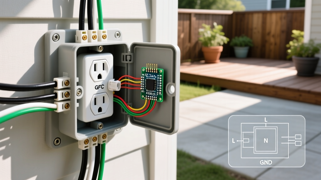
A standard 120V duplex receptacle (commonly called a double outlet) allows two simultaneous plug connections on a single mounting yoke. Whether you are wiring a NEMA 5-15R (15 Amp) or a NEMA 5-20R (20 Amp) device, the physical terminal layout and schematic logic remain identical. The direct answer for standard branch-circuit wiring is: line (hot) connects to the brass screws, neutral connects to the silver screws, and the equipment ground connects to the green screw. Below, we break down the schematic symbols, trace the exact node-by-node path from the panel to the load, and detail how to verify your work with a multimeter.
Decoding the Wiring Diagram for Double Outlet Symbols
Electrical schematics abstract physical devices into standardized symbols. When looking at a National Electrical Code (NEC) compliant wiring diagram for a double outlet, you will encounter specific line styles and geometric shapes that represent the physical circuit. Understanding these prevents dangerous miswiring.
- Hot / Ungrounded Conductor: Represented by a solid black line. In physical space, this is your black (or red) wire carrying 120V RMS relative to ground.
- Neutral / Grounded Conductor: Represented by a dashed line, or a solid line labeled 'W' or 'N'. This is your white (or gray) wire, which carries the return current back to the panel's neutral bus bar.
- Equipment Ground: Represented by a green line, or a black line terminating in a standard three-prong earth symbol (a vertical line with three descending horizontal lines). This is the bare copper or green wire.
- Receptacle Symbol: Drawn as a circle or rectangle with two parallel vertical lines (representing the hot and neutral slots) and a U-shape or circle below them (representing the ground pin). A standard duplex is often shown as two of these symbols stacked or side-by-side on a single bracket.
- Breaker Symbol: A square or rectangle with a toggle line, placed on the hot conductor at the origin of the circuit, indicating the overcurrent protective device (OCPD).
Terminal Mapping and Node-by-Node Path Trace
Before energizing any circuit, you must understand exactly where the electrons travel. A standard duplex receptacle features two sets of terminals (top and bottom) tied together by internal metal bus bars and break-off tabs. Here is the exact terminal mapping for a standard Leviton or Eaton 15A/20A duplex receptacle.
| Terminal Color | Screw Type | Wire Color (NM-B) | Function & Polarity | Torque Spec |
|---|---|---|---|---|
| Brass | Phillips / Slotted | Black (or Red) | Ungrounded (Hot) - Narrow Slot | 14 in-lbs |
| Silver | Phillips / Slotted | White (or Gray) | Grounded (Neutral) - Wide Slot | 14 in-lbs |
| Green | Hex / Slotted | Bare or Green | Equipment Ground - U-Slot | 14 in-lbs |
Node-by-Node Source-to-Load Trace
Follow this textual trace to visualize the complete circuit path, ensuring correct polarity and a continuous ground fault path.
- Node 1 (Source OCPD): The circuit originates at the 15A or 20A single-pole breaker in the main service panel. The breaker's internal bus stabs connect to the hot leg (120V AC).
- Node 2 (Feeder/Branch Cable): Current flows from the breaker into the black wire of a 14/2 or 12/2 NM-B (Romex) cable. Simultaneously, the white neutral wire connects to the panel's neutral bar, and the bare copper wire connects to the panel's ground bar.
- Node 3 (Receptacle Terminals): The cable enters the outlet box. The bare wire lands on the green ground screw, bonding the metal yoke and the U-shaped ground slot to earth. The white wire lands on the silver neutral screw, feeding the internal silver bus and the wider vertical slot. The black wire lands on the brass hot screw, feeding the internal brass bus and the narrower vertical slot.
- Node 4 (The Break-Off Tabs): On the sides of the yoke, small brass and silver metal tabs connect the top and bottom terminal screws. In a standard pass-through wiring diagram, these tabs remain intact, meaning both the top and bottom outlets share the same breaker and neutral.
- Node 5 (Load Connection): When a device is plugged in, the male prongs engage the slots. The hot prong (narrow) contacts the brass bus, the neutral prong (wide) contacts the silver bus, and the ground pin contacts the yoke. Current flows through the appliance and returns via the neutral path.
Verifying Your Connections with a Multimeter
Visual inspection is not enough. According to OSHA electrical safety guidelines and standard commissioning practices, you must verify voltage and continuity before applying a load. Use a CAT III or CAT IV rated digital multimeter (like a Fluke 117 or Klein MM400).
Step 1: De-Energized Continuity Test (Ground Path)
With the breaker OFF and verified dead, set your meter to the continuity (diode/beep) setting. Place one probe on the bare copper wire in the box and the other probe on the U-shaped ground slot of the receptacle face. You should read less than 1.0 ohm (or hear a continuous beep). This confirms the equipment grounding conductor path is unbroken.
Step 2: Energized Voltage Test (Polarity Check)
Turn the breaker ON. Set your multimeter to AC Voltage (V~). Carefully insert the probes into the receptacle slots:
- Hot to Neutral (Narrow to Wide slot): Read should be 120V (acceptable range 114V - 126V). This confirms the circuit is live.
- Hot to Ground (Narrow to U-slot): Read should be 120V. This confirms the ground path is bonded back to the panel and the hot wire is on the correct brass terminal.
- Neutral to Ground (Wide to U-slot): Read should be 0V to 2V. A reading higher than 2V indicates a loose neutral connection upstream or a shared neutral carrying heavy load from another circuit.
Double Outlet Wiring FAQ
Can I wire a double outlet with only two wires (no ground)?
If you are working in an older home with legacy 2-wire (hot and neutral only) knob-and-tube or early NM cable, you cannot install a standard 3-prong grounding receptacle. Per NEC 406.4(D), you have two legal options: replace it with a 2-prong receptacle, or install a GFCI (Ground Fault Circuit Interrupter) receptacle. If you use a GFCI, you must label the faceplate with the included "No Equipment Ground" and "GFCI Protected" stickers. The GFCI will protect against shock, but it will not provide a true ground path for surge protectors.
Why does my wiring diagram for double outlet show a broken brass tab?
If a diagram shows the brass break-off tab removed between the top and bottom hot terminals, it indicates a "split-wired" or "switched" receptacle. This is common in bedrooms or living rooms lacking overhead lighting. In this setup, the top outlet is wired to a standard always-hot breaker, while the bottom outlet is wired to a wall switch. This requires a 3-wire cable (14/3 or 12/3) bringing both an always-hot (black) and a switched-hot (red) to the brass terminals. Note: The silver neutral tab must remain intact unless you are wiring a Multi-Wire Branch Circuit (MWBC) with two separate hot legs on a 240V double-pole breaker.
Does it matter which brass screw I use for the incoming line?
On a standard, non-GFCI duplex receptacle, it does not matter whether the incoming hot wire lands on the top brass screw or the bottom brass screw, provided the break-off tab is intact. The internal brass bus connects them directly. However, if you are wiring a GFCI duplex receptacle, it matters critically. GFCI devices have distinctly marked "LINE" terminals (for incoming power) and "LOAD" terminals (for protecting downstream outlets). Connecting incoming power to the LOAD terminals on a GFCI will result in a dead outlet that will not reset.