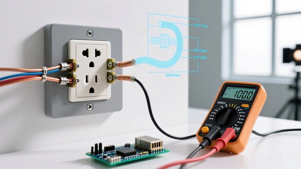
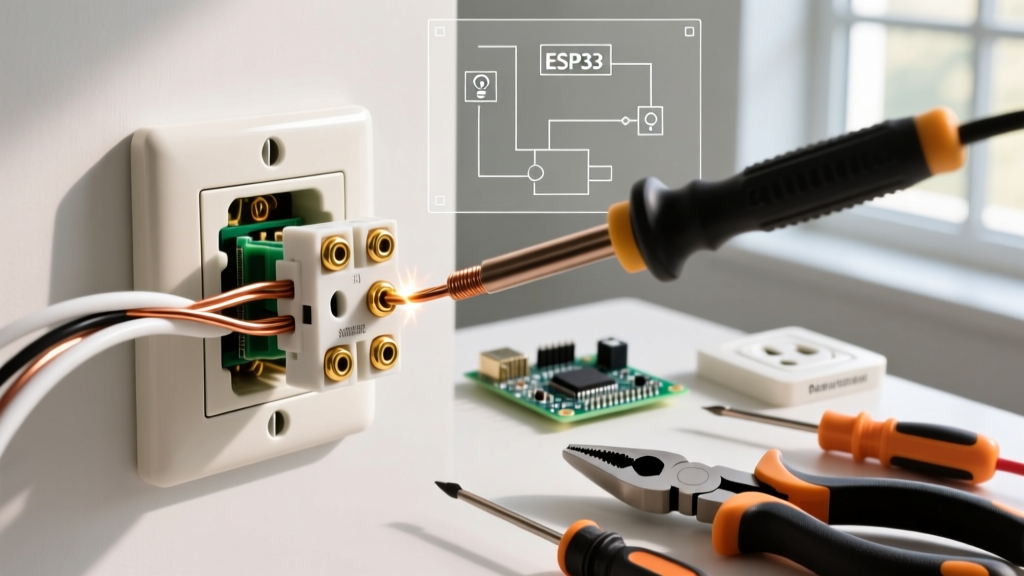
The Problem: 150-Foot Workshop Receptacle Wire Diagram Example
Before we touch the algebra, we need our reference data. Sizing wire isn't just about ampacity; it's about circular mils (CM) to manage resistance over distance. Below is the lookup table derived from NEC Chapter 9, Table 8 and Article 310.16 for stranded copper.
| AWG Size | Circular Mils (CM) | Ampacity (60°C Column) | Ampacity (75°C Column) |
|---|---|---|---|
| 14 AWG | 4,110 | 15A | 20A |
| 12 AWG | 6,530 | 20A | 25A |
| 10 AWG | 10,380 | 30A | 35A |
| 8 AWG | 16,510 | 40A | 50A |
| 6 AWG | 26,240 | 55A | 65A |
Step-by-Step Solution: Sizing the Conductors
Which method applies and why? We use the Single-Phase AC Resistive Voltage Drop Approximation. While AC circuits have reactance, for standard branch circuits under 50A in non-magnetic conduits, the resistive component dominates. The Southwire Voltage Drop Calculator and NEC recommendations rely on this standard formula to size conductors for efficiency rather than just thermal limits.
The formula to find the required Circular Mils (CM) is:
CM = (2 × K × I × L) / VD
Defining our variables:
- K = 12.9 (The DC resistance constant for stranded copper at 75°C, per NEC Chapter 9).
- I = 16A (We use the actual continuous load of the table saw, not the 20A breaker rating).
- L = 150 feet (One-way distance from panel to receptacle).
- VD = 3.6V (Our maximum allowable drop, which is 3% of the 120V nominal source).
Algebra Step 1: Substitute the values into the numerator.
Numerator = 2 × 12.9 × 16 × 150
Numerator = 25.8 × 16 × 150
Numerator = 412.8 × 150
Numerator = 61,920
Algebra Step 2: Divide by the allowable voltage drop (VD).
CM = 61,920 / 3.6
CM = 17,200
Algebra Step 3: Map to the AWG Table.
We need a wire with at least 17,200 Circular Mils. Looking at our table, 8 AWG only provides 16,510 CM. If we used 8 AWG, the drop would be 3.75V (3.12%), which violates our 3% design constraint. Therefore, we must step up to 6 AWG, which provides 26,240 CM.
Sanity Check: Does 6 AWG make sense for a 20A circuit? Thermally, 6 AWG is massively overrated (55A at 60°C). However, 120V circuits suffer voltage drop twice as fast as 240V circuits for the same wattage. Pushing 16A across 150 feet at 120V is a heavy lift. The order of magnitude checks out; stepping up three standard AWG sizes (from 12 to 6) for a 150-foot 120V run is a standard field rule-of-thumb.
Verifying the Answer and Translating the Wire Diagram Example
Math is only half the job. The physical wire diagram example must be executed correctly on the bench. Our diagram specifies a Black (Hot), White (Neutral), and Bare (Equipment Ground) configuration terminating at a 20A GFCI.
How to verify the answer independently: Once installed, do not just trust the math. Plug the 16A table saw in, turn it on, and measure the voltage directly at the receptacle's line-side terminals using a true-RMS meter like a Fluke 117. If your panel outputs 122V, you should read no less than 118.3V at the receptacle under full load. If it reads 114V, your connections have high resistance or the utility voltage is sagging.
Here is where textbook wire diagram examples fail in the real world. A standard 20A GFCI receptacle's back-wire clamps and terminal screws are physically designed for 14 to 10 AWG wire. You cannot terminate 6 AWG wire directly on a 20A GFCI. The wire will not fit in the clamp, or it will strip the terminal screw. To solve this, your wiring diagram must include a pigtail. Use a Wago 221 lever nut or a properly torqued wire nut to transition the 6 AWG feeder to a 12 AWG THHN tail, then land the 12 AWG tail on the GFCI's LINE terminals.
Diagram Symbol Breakdown:
- Single-Pole Breaker (Panel): Connect 6 AWG Black to the breaker lug, 6 AWG White to the neutral bar, and 10 AWG Bare to the ground bar. (Note: Grounding conductors do not carry continuous current, so they do not need to be upsized for voltage drop; a 10 AWG ground is sufficient per NEC 250.122 for a 20A circuit).
- GFCI Receptacle (Load): Land the 12 AWG Black pigtail on the Brass LINE screw, and the 12 AWG White pigtail on the Silver LINE screw. Do not use the LOAD terminals unless you are protecting downstream devices.
FAQ: Common Wire Diagram Example Mistakes
Q: Can I just use 12 AWG wire since it's a 20A breaker?
A: Thermally, yes. 12 AWG is rated for 20A. However, at 150 feet, 12 AWG (6,530 CM) will result in a voltage drop of roughly 9.4V (nearly 8%). Your 120V table saw will see only 112V under load, causing the motor to draw excess amperage, overheat, and potentially trip the breaker or burn out the windings. Always size for voltage drop on long runs.
Q: Why did we use 16A for the calculation instead of the 20A breaker size?
A: Voltage drop is a function of the actual current flowing through the wire, not the rating of the protective device. Since the table saw draws a continuous 16A, calculating at 20A would result in oversized wire and unnecessary copper costs. (Note: If the load was unknown or the circuit was designated for general use, sizing at 80% of the breaker rating—16A—is the correct conservative assumption).
Q: Does the equipment grounding conductor (EGC) need to be 6 AWG too?
A: No. NEC 250.122(B) states that if you upsize ungrounded conductors (Hot/Neutral) for voltage drop, you must proportionally increase the EGC. However, because the EGC only carries current during a fault (a fraction of a second), a 10 AWG copper ground is more than adequate to clear a 20A fault instantly and is standard practice for this wire diagram example.