
Wire color coding for positive and negative is a standardized visual system used to identify the flow direction and potential of direct current (DC) conductors, ensuring safe and consistent connections. In North America and most global DC applications, red is positive (+) and black is negative (-). Getting this right isn't just about neatness or passing an inspection; it dictates whether your circuit functions safely or instantly destroys sensitive electronics upon energization.
The Core Rule: DC Wire Color Codes for Positive and Negative
When working with DC power—whether it's a 12V automotive system, a 24V solar battery bank, or a 5V Arduino breadboard—the color standard is rigid. According to All About Circuits and standard industry practice, the US DC color code is:
- Positive (+): Red
- Negative (-): Black
- Ground / Center-Tap: White or Gray
If you are working with equipment built to European IEC 60446 standards, the DC colors shift. IEC uses Brown for positive, Blue for negative, and Green/Yellow for protective earth. Always check the manufacturer's datasheet if you are integrating imported industrial equipment.
The most dangerous mistake DIYers make is confusing DC positive/negative colors with AC hot/neutral colors. In US AC mains wiring (NEC), black is hot (active current), white is neutral, and bare/green is ground. If you wire a 120V AC inverter output using DC color assumptions (thinking black is just a 'return' path and safe to touch), you create a severe shock hazard. Never assume black means 'safe' or 'negative' without verifying the system type first.
What Changes When You Swap Positive and Negative
Reversing polarity changes the fundamental behavior of a circuit based on the load type. Here is exactly what happens when you swap the red and black wires:
- Resistive Loads (Heaters, Incandescent Bulbs): Nothing changes. A 12V heating element does not care which direction the current flows; it will still generate heat based on Ohm's Law.
- DC Motors: The motor will spin in the exact reverse direction. This is actually a common method for controlling motor direction in simple robotics using a DPDT switch.
- Semiconductors and Electronics (LEDs, ESP32, Inverters): Catastrophic failure. Electrolytic capacitors are polarized; applying reverse voltage causes their internal electrolyte to boil, leading to venting or explosive rupture. Integrated circuits like the NE555 timer or an ESP32-WROOM-32 lack internal reverse-polarity protection on their raw VCC pins. Applying negative voltage to the VCC pin will instantly fry the silicon die.
Think of polarity like a one-way check valve in a plumbing system; if you force water backward against the valve's designed flow, the mechanical seal breaks and the system floods.
Where You Meet This in Practice
You will encounter wire color positive and negative standards most frequently in solar arrays, automotive wiring, off-grid battery banks, and low-voltage LED lighting. However, the physical environment often degrades or obscures these colors.
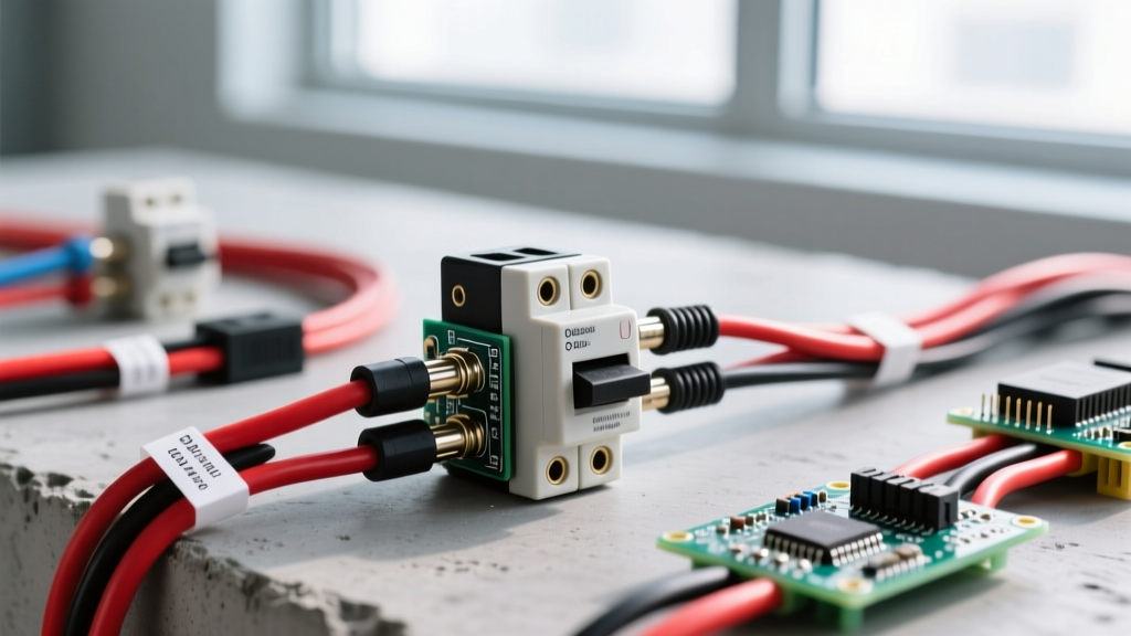
In automotive and marine environments, engine bay heat and UV exposure can fade red wire insulation to a dull pink or orange over a few years. In solar arrays, UV-rated PV wire is often black for both positive and negative to prevent UV degradation, requiring installers to use red and black heat-shrink tubing or electrical tape at every termination point to maintain the color code.
Never blindly trust the wire colors on cheap, imported electronics. I have torn down 12V DC water pumps and generic BMS (Battery Management System) units where the factory used a red wire for ground and a black wire for positive simply because the manufacturer ran out of red wire on the assembly line. Always verify with a multimeter before connecting aftermarket pigtails to your main power bus.
Worked Example: Verifying a 24V LiFePO4 Battery Bank
Let's look at a real-world scenario. You are wiring a 24V 100Ah LiFePO4 battery bank to a 24V-to-120V pure sine wave inverter using 2 AWG red and black stranded welding cable. The inverter requires a 150A ANL fuse on the positive line.
Before bolting down the terminal lugs and inserting the ANL fuse, you must verify the polarity. Here is the exact numeric procedure:
- Set your digital multimeter to DC Volts (200V range).
- Place the red multimeter probe on the exposed copper of the red wire lug.
- Place the black multimeter probe on the exposed copper of the black wire lug.
- Read the display. A fully charged 8S LiFePO4 battery will read between +26.4V and +28.8V.
The Edge Case: If your meter reads -26.4V, your wires are swapped at the battery terminal, or your multimeter probes are reversed. If you connect a reversed negative reading to an inverter equipped with reverse-polarity protection, it will instantly blow its internal DC fuse. If the inverter lacks this protection, the internal MOSFETs will short out, permanently destroying a $400+ piece of equipment. Always trust the meter over the insulation color.
Decision Path: Picking the Right Wire Color and Gauge
Use this decision tree to select the correct wire color and type for your specific DC application. This path terminates in a concrete default recommendation for general use.
| Application Scenario | Required Action / Wire Type | Final Pick / Part |
|---|---|---|
| Low voltage signal / Data (I2C, SPI, UART under 1A) | Use multi-conductor ribbon cable. Red is VCC, Black is GND. | 28 AWG Rainbow Ribbon Cable |
| Automotive / Marine DC (12V/24V, exposed to moisture) | Must use tinned copper to prevent green corrosion. Red/Black. | Ancor Marine Grade 12 AWG Tinned |
| High Current Solar / Inverter (48V DC, >50A) | Use flexible, high-strand-count welding cable. Red/Black. | 2 AWG or 1/0 AWG Red/Black Welding Cable |
| General DIY / Maker Projects (12V/24V DC, up to 30A, indoor) | Standard copper, PVC insulation, easy to strip and terminate. | DEFAULT PICK: Southwire 10 AWG THHN Red and Black |
The Default Recommendation: For 90% of bench builds, solar charge controller wiring, and 12V/24V DC distribution blocks up to 30A, buy a spool of 10 AWG Red and Black THHN stranded copper. It is rated for 30A at 60°C (per NEC Table 310.16), fits perfectly into standard 30A Anderson Powerpole connectors, and the PVC insulation is tough enough to resist abrasion in a DIY enclosure.
Frequently Asked Questions
What if I only have black wire available?
If you are in a pinch and only have black wire, you must physically mark the positive wire at every termination point. Use red heat-shrink tubing or high-quality 3M Super 33+ red electrical tape. Do not rely on a single piece of tape in the middle of a wire run; the marking must be visible exactly where the wire enters the terminal block.
Is white wire ever used for negative?
In standard DC power, no. However, in US telecommunications (RJ45/RJ11) and some specific 48V DC telecom rectifier setups, white or gray can be used as a negative return or center-tap. For general electrical and maker projects, strictly reserve white for AC neutral or DC center-taps to avoid lethal confusion.
Does the ground wire count as negative?
No. In a floating DC system (like a car or a standalone solar setup), the negative terminal is often bonded to the chassis ground, making them electrically identical. However, in a grounded DC system (like a grid-tied solar inverter), the negative conductor carries active return current, while the green/bare ground wire only carries current during a fault. They must remain separate conductors until they meet at the main bonding jumper.