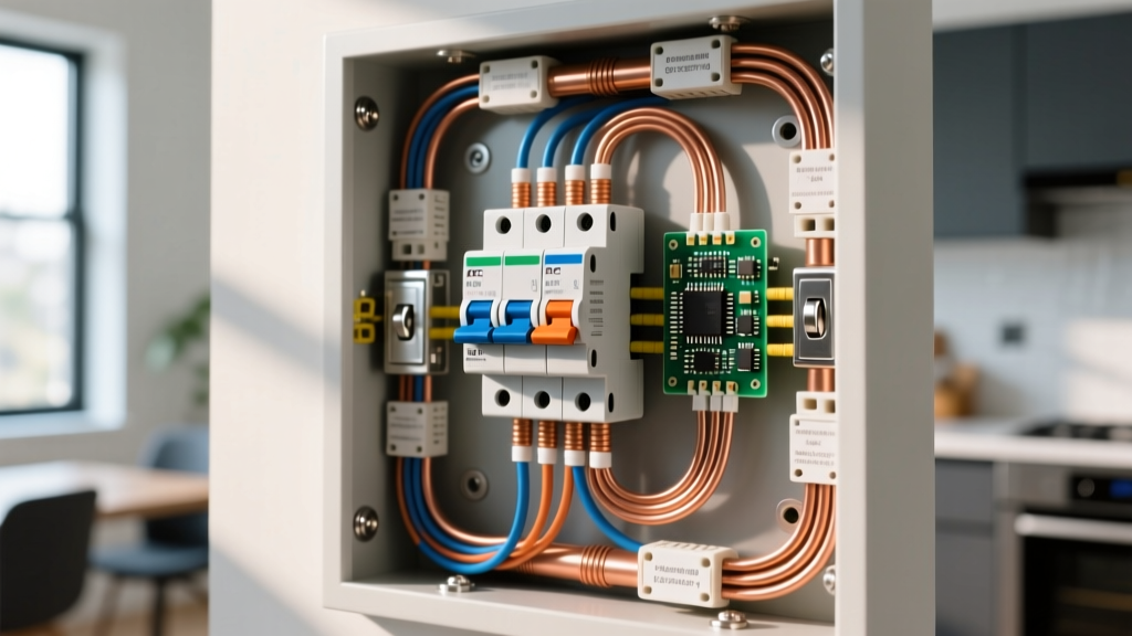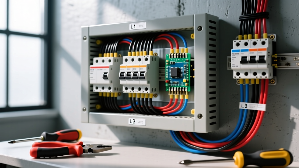

Three phase panel wiring is the method of distributing three alternating currents—offset by 120 electrical degrees—from a main service disconnect to branch circuits and heavy loads via a specialized bus bar arrangement. Unlike residential split-phase systems that pulse power twice per cycle, a three-phase panel delivers continuous, overlapping power peaks, which fundamentally changes how you size conductors, select breakers, and route neutrals in commercial and industrial environments.
The Core Configurations: Wye vs. Delta Voltages
Before pulling any wire, you must identify the transformer configuration feeding your panel. The two dominant three-phase topologies are Wye (Y) and Delta (Δ). Wye systems provide a neutral point, allowing you to pull both three-phase power for motors and single-phase power for lighting from the same panel. Delta systems lack a standard neutral point and are typically reserved for dedicated heavy machinery or specialized distribution. According to NFPA 70 (NEC), identifying the system voltage and configuration dictates your color coding, breaker selection, and grounding electrode requirements.
| Configuration | Line-to-Line Voltage | Line-to-Neutral Voltage | Primary Application |
|---|---|---|---|
| 208Y/120V Wye | 208V | 120V | Commercial offices, retail lighting, standard HVAC |
| 480Y/277V Wye | 480V | 277V | Industrial plants, large commercial lighting, heavy motors |
| 240V Delta (High-Leg) | 240V | 120V / 208V / 120V | Older commercial buildings, mixed lighting and motor loads |
| 480V Delta (Ungrounded/Corner) | 480V | N/A (No Neutral) | Specialized industrial manufacturing, legacy mining equipment |
What Three Phase Panel Wiring Changes in a Real Installation
Transitioning from single-phase to three-phase panel wiring alters the physics of your installation in three critical ways:
- Conductor Sizing (The √3 Advantage): Three-phase power delivers more wattage per ampere. The power formula shifts from P = V × I to P = √3 × V × I × Power Factor. Because of the 1.732 multiplier, you can transmit the same amount of power using significantly smaller wire gauges compared to single-phase, reducing copper costs and conduit fill ratios.
- Neutral Conductor Cancellation: In a Wye system, if the three phase loads are perfectly balanced, the vector sum of the currents returning on the neutral bus is zero. While NEC Article 220 requires you to size the neutral for the maximum unbalanced load, heavily balanced three-phase panels often allow for reduced neutral feeder sizing compared to the phase conductors.
- Breaker Mechanics and Fault Clearing: Three-phase panels utilize 3-pole breakers with internal common-trip mechanisms. If a fault occurs on Phase A, the breaker mechanically forces Phases B and C open simultaneously. This prevents 'single-phasing,' a condition where a three-phase motor continues running on only two legs, which rapidly burns out the motor windings due to severe current imbalance.
Worked Example: Sizing Feeders for a 15 HP 460V Motor
Let's calculate the exact breaker and wire size for a 15 HP, 460V, three-phase AC motor installed in a 480Y/277V panel. This requires navigating multiple NEC tables, as motor circuits have unique sizing rules that override standard branch circuit logic.
Step 1: Find Full-Load Current (FLC)
Do not use the nameplate Full-Load Amps (FLA) for wire sizing. NEC 430.6 requires using the standardized FLC from NEC Table 430.250. For a 15 HP motor at 460V, the table dictates an FLC of 21 Amps.
Step 2: Size the Conductors
NEC 430.22 requires motor branch circuit conductors to be sized at 125% of the FLC.
21A × 1.25 = 26.25 Amps.
Looking at NEC Table 310.16 (using the 75°C column for standard terminations), 10 AWG THHN copper wire is rated for 35 Amps. Therefore, 10 AWG is our minimum phase conductor size.
Step 3: Size the Short-Circuit / Ground-Fault Breaker
Standard breakers are sized to protect the wire, but motor breakers are sized to allow the motor to start without tripping. NEC 430.52 allows an inverse-time breaker sized up to 250% of the FLC for standard AC motors.
21A × 2.50 = 52.5 Amps.
Per NEC 240.6, if the calculation does not match a standard breaker size, you are permitted to round up to the next standard size. The next standard size above 52.5A is 60 Amps. You will install a 60A, 3-pole breaker.
Step 4: Set the Overload Protection
This is where the nameplate matters. Overloads protect the motor itself from thermal damage. If the motor nameplate lists an FLA of 19.5A and a service factor of 1.15, NEC 430.32 dictates sizing the overload heaters at 125% of the nameplate FLA.
19.5A × 1.25 = 24.3 Amps. You will dial the starter's solid-state overload relay to exactly 24.3A.
Where You Meet This in Practice and Common Confusions
You will primarily encounter three phase panel wiring in commercial rooftop units (RTUs), machine shops running CNC mills, and modern EV DC fast-charging stations. A typical Level 3 DC fast charger pulls 480V three-phase power, converting it internally to supply up to 350kW to a vehicle battery. In these environments, understanding the nuances of three-phase distribution is critical for preventing equipment failure.
The most common confusion in the field is mixing up 208V three-phase and 240V single-phase (split-phase). Many commercial buildings supply 208Y/120V panels. If an installer wires a piece of equipment rated strictly for 240V single-phase (like a heavy resistive heater or a specific air compressor) across two legs of a 208V three-phase panel, the equipment will operate at only 75% of its designed power output (P = V²/R). Motors will run hot, sluggish, and eventually trip their thermal overloads. Always verify the supply voltage with a true-RMS multimeter before terminating heavy loads.
Frequently Asked Questions
Can I use a 3-pole breaker for a single-phase 208V load?
No. While a 3-pole breaker will physically fit and protect the circuit, it wastes a pole and violates the principle of selective coordination. Use a 2-pole breaker for single-phase line-to-line loads, leaving the third phase available for balanced three-phase loads.
Why does my 480V panel not have a neutral bar?
If your panel is fed by a 480V Delta transformer (rather than a 480Y/277V Wye), there is no neutral point generated at the source. These panels are strictly for three-phase motor loads and 480V line-to-line equipment. If you need 277V for lighting, you must install a step-down transformer to create a derived Wye neutral.
How do I verify phase rotation before starting a new motor?
Never guess phase rotation (A-B-C vs A-C-B) on three-phase compressors or pumps, as reverse rotation can destroy the mechanical components in seconds. Use a dedicated phase rotation meter (like the Fluke 9040) at the motor terminals while the disconnect is locked out, verifying the sequence matches the manufacturer's schematic before energizing.
For deeper theoretical analysis of vector mathematics in Wye and Delta topologies, refer to the All About Circuits textbook chapter on three-phase configurations. Always consult your local Authority Having Jurisdiction (AHJ), as local amendments to the NEC may dictate specific derating factors or grounding electrode requirements for your specific region.