
A single pole single throw switch (SPST) is the most fundamental on/off control in electrical design, routing one circuit through one set of contacts. If you are switching a simple resistive load under 20A manually, a standard mechanical toggle like the Carling 110-series is your default. If you need logic-level control, galvanic isolation, or are switching high-inrush inductive loads, you step up to an electromechanical SPST relay like the Omron G2R-1-E. This guide breaks down exactly how to read the datasheet, wire the coil and contact sides, and pick the right part for your specific load.
The SPST Baseline: Mechanical Switches vs. Electromechanical Relays
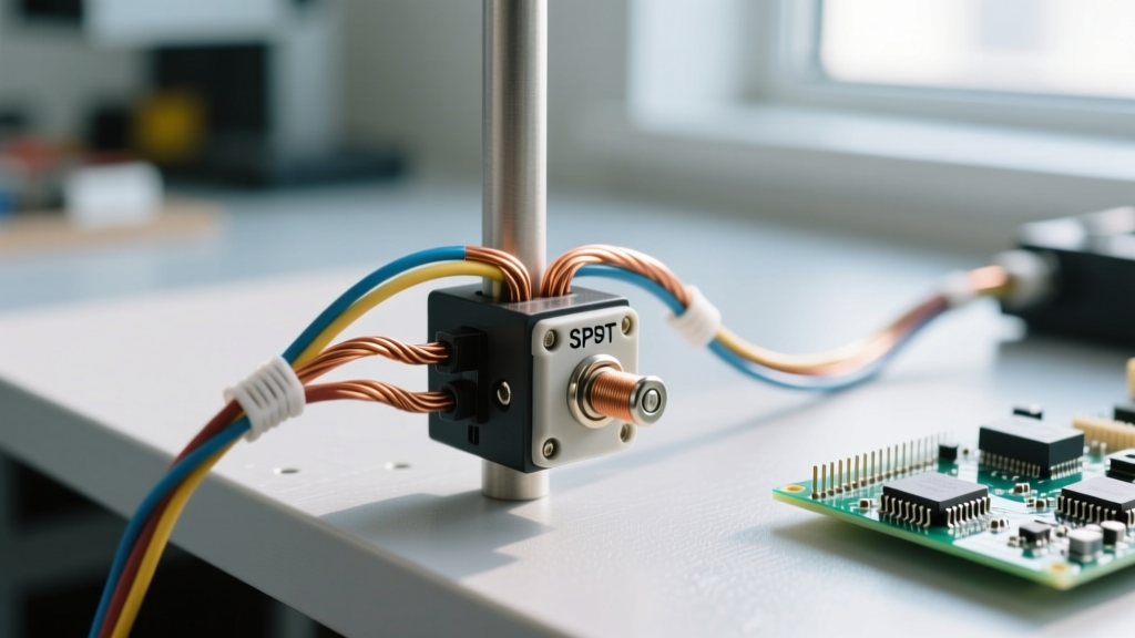
The term SPST defines the contact arrangement: one input (pole) and one output (throw). However, the actuation method splits the category into two distinct hardware families:
- Mechanical SPST Switches: Actuated by human force (toggle, rocker, pushbutton). The physical link between the actuator and the contacts means no isolation between the user and the load circuit. Rated for direct branch-circuit or appliance wiring.
- Electromechanical SPST Relays: Actuated by a magnetic coil. When you apply voltage to the coil, it pulls the single throw contact closed. This provides galvanic isolation between your low-voltage control circuit (the coil) and your high-voltage/high-current load circuit (the contacts).
Decoding the Datasheet: Which Rating Column Governs Your Load?
The most common cause of SPST switch failure is sizing the component based on its maximum resistive rating, then applying it to a motor. Datasheets list multiple ratings governed by IEC 60947 standards. Here is how to read the rating table and determine which column governs your specific application.
| Load Type | Governing Rating Column (IEC) | Typical Inrush Multiplier | Example Part Limit (Omron G2R-1-E) |
|---|---|---|---|
| Resistive (Heaters, Incandescent) | AC-1 / DC-1 (Cos φ ≈ 1.0) | 1x to 1.5x | 10A at 250VAC |
| Inductive (Solenoids, Transformers) | AC-11 / DC-13 (Cos φ ≈ 0.4) | 2x to 5x | 3A at 250VAC |
| Motor (Squirrel Cage, Compressors) | AC-3 (Locked Rotor Amps) | 6x to 10x | Not recommended (Use contactor) |
| Capacitive (LED Drivers, Power Supplies) | Peak Inrush Current Rating | 10x to 50x | Must check specific inrush curve |
Which column governs? Always look at the power factor (Cos φ) or the specific IEC utilization category. If you are switching a 120VAC solenoid valve that draws 2A steady-state, you do not look at the 10A AC-1 resistive column. You look at the AC-11 inductive column, which might derate that exact same switch to 3A. The governing column is always the one that matches the load's impedance characteristics.
Furthermore, breaking capacity is drastically lower for DC than AC. AC voltage crosses zero 120 times a second (in 60Hz systems), naturally extinguishing the arc when contacts open. DC voltage never crosses zero, meaning the arc will sustain until the contacts are physically far enough apart or the metal vaporizes. A switch rated for 10A at 250VAC might only be rated for 2A at 30VDC.
Wiring the Coil and Contact Sides (Plus DC Flyback Protection)
When wiring an electromechanical SPST relay, you are dealing with two completely isolated circuits: the coil side (control) and the contact side (load).
The Coil Side (Control Circuit)
The coil is simply an inductor. You wire your control voltage (e.g., 12VDC, 24VDC, or 120VAC) across the A1 and A2 terminals. Polarity does not matter for standard DC coils unless the relay has a built-in indicator LED or suppression diode, in which case the datasheet will mark A1 as positive.
The Contact Side (Load Circuit)
The load circuit wires to the Common (COM) and Normally Open (NO) terminals. For an SPST-NO relay, the circuit is open until the coil pulls the armature closed. Always use ferrules on stranded wire when terminating into screw-clamp relay bases to prevent stray strands from shorting against adjacent terminals. Torque the terminal screws to the manufacturer's spec (typically 0.5 to 0.8 Nm for standard 10A relays) to prevent thermal runaway from loose connections.
Load-Type Decision Tree: Picking the Exact Part Number
Use this decision path to terminate your component search with a concrete, proven part number. Do not guess; match the load physics to the hardware.
| IF your load is... | AND your control is... | THEN select this exact part: |
|---|---|---|
| Resistive (e.g., 120VAC space heater, 12A) | Manual human actuation | Carling 110-110 (20A 125/250VAC SPST Toggle, ~$6.50) |
| Inductive (e.g., 24VDC solenoid valve, 1.5A) | Arduino/ESP32 GPIO via driver | Omron G2R-1-E DC12 (16A SPST-NO Relay + 1N4007 diode, ~$4.00) |
| Motor (e.g., 1/4 HP 120VAC exhaust fan) | Manual wall switch | Leviton 1491 (15A 120/277VAC AC-3 Motor Rated Toggle, ~$9.00) |
| High DC Current (e.g., 48VDC solar disconnect, 30A) | Manual or low-voltage trigger | Blue Sea Systems 9001P (e-Series Battery Switch, handles high DC arc, ~$35.00) |
Source reference: For detailed relay contact life curves and derating data, consult the All About Circuits relay specification guide or manufacturer application notes.
Bench Testing: Dead and Live Verification
Before installing any SPST switch or relay into a live panel, verify its mechanical and electrical integrity on the bench.
Dead Testing (Continuity and Coil Resistance)
- Set your multimeter to Continuity/Resistance (Ω).
- Test the Contacts: Place probes across COM and NO. It should read Open Loop (OL). Actuate the switch (or apply rated voltage to the relay coil). The meter must drop to < 0.1 Ω. If it reads higher, the contacts are oxidized or pitted.
- Test the Coil (Relays only): Place probes across A1 and A2. You should read a specific resistance (e.g., a 12VDC Omron G2R coil typically reads around 275 Ω). If it reads OL, the coil is burned open. If it reads near 0 Ω, the coil is shorted.
Live Testing (Voltage Drop under Load)
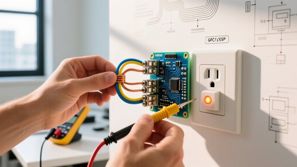
Once installed and powered, the true test of a switch is its voltage drop under full load. Set your multimeter to DC or AC Volts (mV range if possible). Place one probe on the line-side terminal and the other on the load-side terminal while the switch is closed and the load is running.
- Acceptable: < 50 mV drop.
- Warning: 50 mV to 200 mV drop. The contacts are degrading; schedule a replacement.
- Critical: > 200 mV drop. The switch is generating significant heat (P = I × V_drop). Shut down and replace immediately to prevent a fire hazard.
Repair vs. Replace: When to Trash a Pitted SPST
There is a persistent myth in hobbyist circles that you can file down pitted relay contacts to restore them. This is dangerous and incorrect for modern components. Here is the hard rule for repair versus replacement.
Default Recommendation: REPLACE. Any SPST switch or relay operating at mains voltage (AC or DC) or carrying more than 1A of current that shows visible pitting, carbon tracking, or measures > 0.5 Ω contact resistance must be discarded. Modern relay contacts are often plated with a microscopically thin layer of silver-tin-oxide or gold. Filing them removes this plating, exposing the base metal to rapid oxidation and guaranteed welding on the next high-inrush cycle. For a comprehensive look at failure modes, reference Macromatic's technical breakdown on relay contact failure.
The Only Exception (Repair): You may attempt to clean contacts only if the switch is used for low-voltage, low-current signal routing (e.g., < 5VDC, < 100mA audio or data switching). In these cases, the 'dry circuit' contacts suffer from insulating oxide buildup, not arcing pitting. You can restore them by sliding a piece of heavy kraft paper soaked in 99% isopropyl alcohol between the closed contacts, then pulling it out while applying light contact pressure. Never use sandpaper, emery cloth, or contact cleaners containing lubricants on signal relays.
By matching the IEC utilization category to your load physics, protecting DC coils with flyback diodes, and enforcing strict voltage-drop testing, your SPST switching circuits will operate reliably for their entire rated mechanical lifespan.