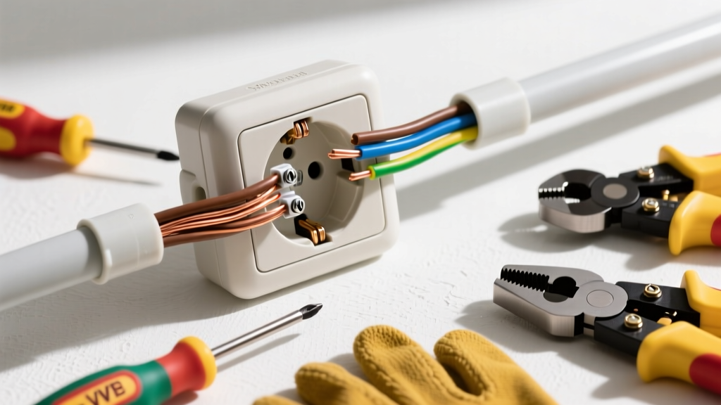
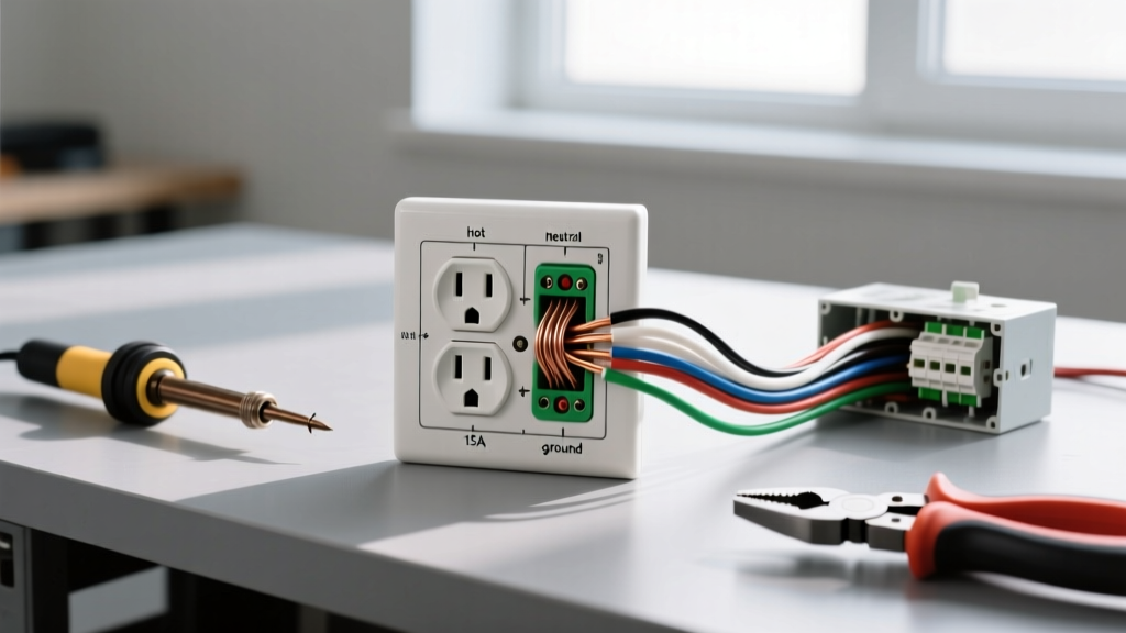
When you search for a gfci outlet image, you are usually staring at the back of a receptacle trying to decipher the physical difference between the LINE and LOAD terminals. A Ground Fault Circuit Interrupter (GFCI) is a critical life-safety device that protects against lethal shock by monitoring current imbalance between the hot and neutral conductors. If the GFCI detects a leakage of just 5 milliamps to ground, it trips the internal relay in under 25 milliseconds.
Getting the wiring right is non-negotiable. Misinterpreting the terminal layout can result in a dead circuit, a false sense of security, or a downstream failure. This guide breaks down the physical layout of a standard 20A GFCI, provides a precise terminal mapping table, and walks you through a code-compliant installation for a kitchen or bathroom branch circuit.
Tools, Materials, and Device Ratings
Before opening the electrical box, ensure you have the correct materials for a 20-amp branch circuit. Under NEC-style guidance, kitchens and bathrooms require 20A circuits, which dictates your wire gauge and device rating.
Materials List
- Receptacle: 20A GFCI duplex receptacle (e.g., Leviton GFNT2-W or Eaton GF20W). Note: A 20A GFCI will accept both 15A (NEMA 1-15) and 20A (NEMA 5-20) plugs.
- Wire: 12/2 NM-B cable with ground (for standard drywall cavities) OR 12 AWG THHN copper conductors (if pulling through EMT conduit).
- Breaker: 20A single-pole standard thermal-magnetic breaker. (Do not use a GFCI breaker if you are installing a GFCI receptacle; the redundant trip curves can cause nuisance tripping and coordination issues).
- Connectors: Ideal Wire-Nuts (yellow or red) or Wago 221 lever nuts for pigtailing.
Required Tools
- Non-contact voltage (NCV) tester (e.g., Klein NCVT-1)
- Digital multimeter (DMM) with CAT III rating
- Wire strippers calibrated for 12 AWG and 14 AWG
- Insulated torque screwdriver (capable of 14 in-lbs)
- 3-light GFCI circuit analyzer (e.g., Gardner Bender GFI-3501)
Decoding the GFCI Outlet Image: Terminal Mapping
The back of a GFCI receptacle looks vastly different from a standard duplex outlet. Instead of two brass and two silver screws, you will find a set of terminals labeled LINE and a separate set labeled LOAD, often covered by a yellow piece of electrical tape from the factory. The LINE terminals receive incoming power from the breaker panel. The LOAD terminals feed power to downstream standard receptacles, extending GFCI protection to them.
Here is the exact terminal mapping for a standard 20A GFCI installation where the device is protecting only itself (the most common configuration).
| Terminal Label | Screw Color | Wire Color to Land | Function | Torque Spec (12 AWG) |
|---|---|---|---|---|
| LINE Hot | Brass | Black | Receives 120V incoming feed from breaker | 14 in-lbs |
| LINE Neutral | Silver | White | Receives incoming neutral return path | 14 in-lbs |
| LOAD Hot | Brass | None (leave taped) | Feeds downstream hot (if applicable) | 14 in-lbs |
| LOAD Neutral | Silver | None (leave taped) | Feeds downstream neutral (if applicable) | 14 in-lbs |
| Ground | Green | Bare / Green | Equipment grounding conductor (EGC) | 14 in-lbs |
Mains Safety Protocol: De-Energize and Verify
- Locate and Switch Off: Turn off the 20A breaker supplying the bathroom or kitchen circuit at the main service panel.
- Initial Sweep: Use your NCV tester to scan the faceplate and the wires inside the box. The tester should remain silent and unlit.
- Multimeter Verification: Set your DMM to AC Voltage (V~). Insert the probes into the slots of the existing receptacle (Hot to Neutral, Hot to Ground). The reading must be exactly 0.0V. If you read any voltage above 2V, stop immediately; you have turned off the wrong breaker or have a shared-neutral (multi-wire branch circuit) scenario.
Step-by-Step GFCI Wiring Procedure
For this installation, we are using the 'back-wire' clamp plate method, which is vastly superior to looping the wire around the screw head for 12 AWG solid copper. The clamp plate provides a larger surface area, resists pull-out, and ensures consistent pressure.
- Prep the Conductors: Strip exactly 5/8 inch of insulation from the black, white, and bare copper wires. Do not strip too much; exposed copper outside the terminal housing is a shock hazard and a direct NEC violation.
- Terminate the Ground: Insert the bare copper ground wire into the back-wire hole adjacent to the green ground screw. Tighten the green screw to 14 in-lbs. If the box is metal, you must also run a 12 AWG green grounding pigtail from the receptacle's green screw to the metal box's grounding clip or tapped hole.
- Terminate LINE Neutral: Identify the incoming neutral wire (it will be grouped with the incoming hot, not the downstream neutrals). Insert the white neutral wire into the back-wire hole next to the silver LINE screw. Tighten to 14 in-lbs.
- Terminate LINE Hot: Insert the black hot wire into the back-wire hole next to the brass LINE screw. Tighten to 14 in-lbs.
- Cap Unused Wires: If you have downstream cables in the box that are being fed by a different circuit or do not require GFCI protection, cap their black and white wires individually with wire nuts. Do not land them on the LOAD terminals.
- Fold and Secure: Carefully fold the wires into the back of the electrical box. Push the GFCI receptacle flush against the box and secure it with the provided 6-32 mounting screws. Attach the faceplate.
Line vs. Load: When to Use Downstream Terminals
A common point of confusion when studying a GFCI outlet image is the purpose of the LOAD terminals. You only use the LOAD terminals if you want the GFCI to protect standard receptacles located further down the circuit (e.g., protecting a standard outlet next to the bathroom mirror).
If you are wiring a LOAD circuit, the black downstream wire lands on the brass LOAD screw, and the white downstream wire lands on the silver LOAD screw. However, modern best practice—and the preference of most professional electricians—is to pigtail all hots and neutrals to the LINE terminals, providing GFCI protection only at the point of use. This prevents a single tripped GFCI in a bathroom from killing power to a downstream bedroom outlet on the same circuit, which confuses homeowners and complicates troubleshooting.
Verify, Test, and Troubleshoot
Once the device is physically installed, you must verify electrical integrity and mechanical function before considering the job complete.
Expected Meter Readings
Turn the 20A breaker back on at the panel. Set your DMM to AC Voltage. Measure from the shorter slot (Hot) to the longer slot (Neutral). You should read between 114V and 126V (nominal 120V). Measure from Hot to the U-shaped Ground slot; it should read the same. If you read 240V, you have a severe panel wiring fault. If you read 0V, the breaker is tripped or the LINE wires are not making contact.
The 3-Light Tester Check
Plug a 3-light GFCI circuit analyzer into the receptacle. For a correctly wired circuit, the tester should illuminate two amber/yellow lights (the 'Correct' indicator). Press the black TEST button on the analyzer. The GFCI should audibly click and cut power to the tester. Press the RESET button on the face of the GFCI; power should restore.
The Most Common Botch: Reversing LINE and LOAD
The most frequent error made by DIYers is landing the incoming power wires on the LOAD terminals instead of the LINE terminals.
The Symptom: If you wire the feed to LOAD, the GFCI receptacle will typically remain completely dead. This happens because the internal line-side monitoring circuit and the silicon-controlled rectifier (SCR) that powers the trip solenoid are not energized. In some older or specific manufacturer designs, the receptacle might power up, but pressing the TEST button will do absolutely nothing because the sensing coil cannot detect the simulated fault correctly.
The Fix: De-energize the circuit, pull the device out, and move the incoming black and white wires from the LOAD terminals to the LINE terminals. Never assume a dead GFCI is defective until you have verified the incoming power is actually on the LINE side.
For more information on the life-saving statistics of GFCI technology and code requirements, refer to the Consumer Product Safety Commission (CPSC) GFCI guidelines and the National Fire Protection Association (NFPA) NEC resources.