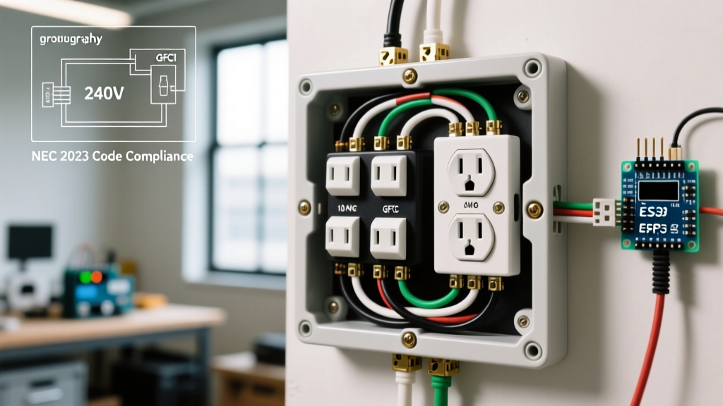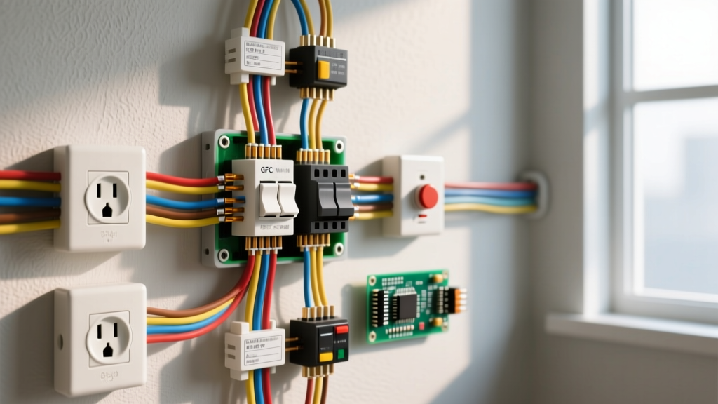

When you look at basic wiring diagrams for residential branch circuits, the most common point of failure for DIYers isn't the physics—it is misinterpreting the physical terminals versus the schematic symbols. A schematic shows logical connections; a wiring diagram shows physical routing. If you are wiring a 120V Ground Fault Circuit Interrupter (GFCI) to protect downstream standard receptacles, confusing the 'Line' and 'Load' terminals will result in a dead downstream circuit or a GFCI that fails to trip under fault conditions.
Before we trace the circuit, here are the baseline specifications for a standard modern kitchen or bathroom 20A branch circuit. These values assume copper conductors in a standard 30°C ambient environment.
| Parameter | Required Value | NEC Reference / Notes |
|---|---|---|
| Breaker Size | 20A Single-Pole | NEC 210.20(A) |
| Wire Gauge (NM-B) | 12 AWG Copper | NEC 310.16 (60°C column for NM-B) |
| Receptacle Rating | 20A (or 15A on 20A circuit) | NEC 210.21(B)(3) |
| Terminal Torque | 14 in-lbs (1.6 N-m) | NEC 110.14(D) / Manufacturer Spec |
Decoding the Symbols in Basic Wiring Diagrams
Basic wiring diagrams use a mix of standardized schematic symbols and physical device representations. Understanding what each symbol means in the context of your specific drawing prevents miswiring. Below is the legend for the symbols used in a standard GFCI-to-downstream wiring diagram.
| Symbol on Diagram | Physical Device | Function in this Circuit |
|---|---|---|
| Single-pole switch with '20' label | 20A Circuit Breaker | Overcurrent protection; feeds the GFCI Line. |
| Receptacle with 'TEST/RESET' buttons | GFCI Receptacle | Provides ground-fault protection for itself and downstream devices via the Load terminals. |
| Standard duplex receptacle symbol | Standard 15A/20A Receptacle | Downstream load; protected by the upstream GFCI. |
| Solid line with hash marks or 'GND' | Bare Copper / Green Insulated Wire | Equipment grounding conductor; provides a low-impedance fault path back to the panel. |
| Circle with a cross or wire twist | Wire Nut / Wago Connector | Splice point for pigtailing grounds or extending neutrals. |
Node-by-Node Trace: Panel to GFCI to Downstream Load
To properly wire the circuit, we must trace the current path from the source (breaker panel) through the GFCI sensing toroid, and out to the downstream load. This trace explicitly defines polarity and the ground path.
Node 0: The Source (Breaker Panel)
The 20A single-pole breaker connects to the hot bus bar. A 12/2 NM-B cable exits the panel. The black (hot) wire connects to the breaker terminal. The white (neutral) wire connects to the neutral bus bar. The bare (ground) wire connects to the equipment grounding bus bar.
Node 1: GFCI LINE Terminals (Source to Device)
The 12/2 NM-B cable enters the GFCI electrical box. The black hot wire connects to the brass screw marked LINE HOT. The white neutral wire connects to the silver screw marked LINE NEUTRAL. Polarity is critical here: if you reverse hot and neutral on the Line side, the GFCI will still power, but it will fail to trip during a ground fault because the internal sensing toroid will read the current return path incorrectly.
Node 2: GFCI LOAD Terminals (Device to Downstream)
A second 12/2 NM-B cable exits the GFCI box toward the downstream outlet. The black wire of this second cable connects to the brass screw marked LOAD HOT. The white wire connects to the silver screw marked LOAD NEUTRAL. These terminals are physically located downstream of the GFCI's internal sensing electronics.
Node 3: Downstream Standard Receptacle
The second cable enters the standard receptacle box. The black wire connects to the brass (hot) terminal. The white wire connects to the silver (neutral) terminal.
Terminal Mapping and Physical Device Connections
When you flip a 20A GFCI receptacle (like a Leviton SmartlockPro or Pass & Seymour Self-Test model) over, the back is crowded with screws and clamp plates. Here is exactly which terminal is which on the physical device, mapped to your wiring diagram.
| Physical Terminal Location | Screw Color / Marking | Wire Color to Connect | Function & Notes |
|---|---|---|---|
| Top-Right (Typically) | Brass / 'LINE' | Black (Incoming Hot) | Feeds power from the breaker to the GFCI internals. |
| Top-Left (Typically) | Silver / 'LINE' | White (Incoming Neutral) | Provides the return path to the panel neutral bus. |
| Bottom-Right (Typically) | Brass / 'LOAD' | Black (Outgoing Hot) | Feeds protected hot to downstream receptacles. |
| Bottom-Left (Typically) | Silver / 'LOAD' | White (Outgoing Neutral) | Feeds protected neutral to downstream receptacles. |
| Bottom-Center | Green / 'GND' | Bare Copper (Ground Pigtail) | Bonds the device yoke to the equipment grounding system. |
Side-Wiring vs. Back-Wiring: Modern 20A GFCIs feature 'back-wire' clamp plates under the terminal screws. Do not confuse these with the cheap 'push-in' stab connections found on old standard receptacles. Back-wire clamps are highly secure and allow you to insert a straight-stripped 12 AWG wire under the plate, then tighten the screw. If your diagram specifies 14 in-lbs of torque, use a calibrated torque screwdriver. Hand-tightening often results in 8-10 in-lbs, which can cause terminal heating and voltage drop over time under a continuous 16A load.
Verifying Your Connections with a Multimeter
Never assume the wiring is correct just because the reset button clicks. You must verify the circuit with a multimeter (such as a Fluke 117 or equivalent CAT III rated meter) before plugging in any loads. According to Fluke's official testing guidelines, verifying both voltage and ground impedance is critical for GFCI operation.
Step 1: Dead-Front Continuity Test (Breaker OFF)
Before energizing, set your meter to Continuity/Ohms. Measure across the Line Hot (black) and Line Neutral (white) at the panel end. You should read 'OL' (Open Loop). If you read near 0 ohms, you have a dead short in the cable—do not turn the breaker on. Next, measure from the bare ground wire to the neutral bus bar; it should read near 0 ohms, confirming the ground/neutral bond at the main panel.
Step 2: Live Voltage Verification (Breaker ON)
Turn on the 20A breaker. Set your meter to AC Voltage (V~).
1. Line to Neutral: Probe the brass Line screw and silver Line screw on the GFCI. Expected: 114V - 126V.
2. Line to Ground: Probe the brass Line screw and the green ground screw. Expected: 114V - 126V.
3. Neutral to Ground: Probe the silver Line screw and green ground screw. Expected: < 2.0V (ideally < 0.5V). A high reading here indicates a loose neutral connection upstream.
Step 3: Downstream Load Verification
Press the 'RESET' button on the GFCI. Go to the downstream standard receptacle.
1. Hot to Neutral: Probe the shorter slot (hot) and longer slot (neutral). Expected: 114V - 126V.
2. Hot to Ground: Probe the shorter slot and the round ground hole. Expected: 114V - 126V.
If you read 0V at the downstream outlet but 120V at the GFCI Line terminals, you have either miswired the Load terminals (swapped Line and Load on the GFCI) or have a broken conductor in the second cable run.
Step 4: The Trip Test
While a multimeter verifies voltage, it cannot verify the GFCI's internal trip coil. Use a dedicated GFCI receptacle tester (like the Gardner Bender GFI-3501) or press the physical 'TEST' button on the device. The downstream outlet must lose power, and the GFCI must physically click and pop the RESET button out. If the downstream outlet stays live when you press TEST, your Load and Line wires are reversed on the GFCI, rendering the downstream protection completely non-functional—a severe shock hazard that violates NEC Article 210.8 requirements for ground-fault protection.