
Understanding the Core Parts of an Electrical Outlet
When approaching a DIY receptacle replacement, identifying the specific parts of an electrical outlet is the first step toward a safe, code-compliant installation. Modern 15-amp and 20-amp duplex receptacles are engineered with multiple fail-safes, but improper wiring remains a leading cause of residential electrical fires. According to the National Fire Protection Association (NFPA), adherence to the National Electrical Code (NEC) regarding terminal connections and tamper resistance is non-negotiable.
1. The Yoke (Mounting Strap)
The metal frame that holds the receptacle body is the yoke. It features mounting holes for the box screws and a plaster ear for alignment. Crucially, the yoke houses the break-off tabs on the hot (brass) and neutral (silver) sides. Snapping these tabs with needle-nose pliers isolates the top and bottom receptacles, a necessary step for split-wired (switched) outlets.
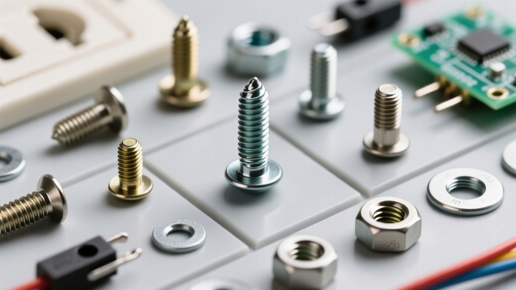
2. Terminal Screws and Binding Plates
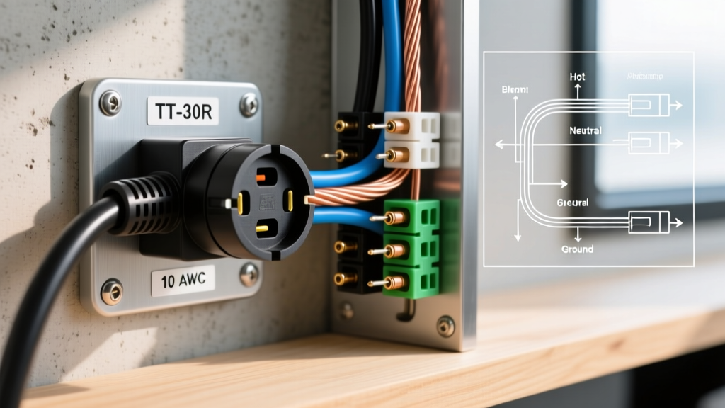
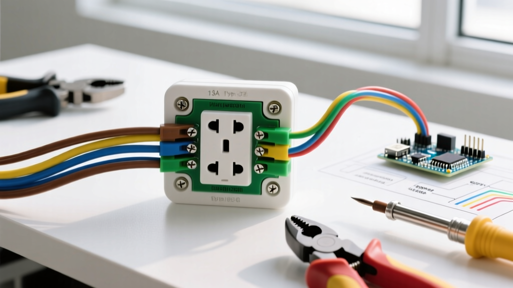
- Brass Screws (Hot): Connect to the black (or red) line wire.
- Silver Screws (Neutral): Connect to the white grounded wire.
- Green Screw (Ground): Connect to the bare copper or green insulated ground wire.
Expert Insight: Always use the side-wire terminal screws with a binding plate rather than the push-in (backstab) holes on the rear. Backstab connections rely on a small internal spring that can loosen over time due to thermal expansion, leading to arcing and melted yokes.
3. Tamper-Resistant (TR) Shutters
Inside the face of the receptacle slots are internal plastic shutters. Mandated by the NEC for all new residential installations, these shutters require simultaneous, equal pressure on both the hot and neutral slots to open. This prevents children from inserting single objects like paperclips into the hot slot. You can identify TR outlets by the letters "TR" stamped on the face.
Receptacle Comparison Matrix: Standard vs. TR vs. GFCI
| Feature | Standard Duplex (Non-TR) | Tamper-Resistant (TR) | GFCI Receptacle |
|---|---|---|---|
| Internal Shutters | No | Yes | Yes |
| Average Cost (2026) | $1.50 - $2.50 | $3.00 - $6.00 | $15.00 - $25.00 |
| NEC Compliance (New Build) | Prohibited | Required (General Rooms) | Required (Wet/Damp Areas) |
| Recommended Model | N/A (Retrofit only) | Leviton T5325-W | Leviton GFNT1-W |
For a comprehensive look at compliant residential receptacles, refer to the Leviton Residential Receptacles catalog.
Step-by-Step Installation Guide
Replacing an outlet requires precision. The U.S. Consumer Product Safety Commission (CPSC) emphasizes that proper wire preparation and torque are critical to preventing electrical fires.
Step 1: Kill the Power and Verify
Turn off the circuit breaker. Use a non-contact voltage tester (NCVT) to test the top and bottom slots of the existing outlet. Follow up by removing the faceplate and testing the side terminal screws directly to ensure no backfed voltage is present.
Step 2: Prepare the Wires
Inspect the wire ends. If they are scorched, heavily oxidized, or bent, snip them back to clean copper. Use the wire stripping gauge built into the back of the new receptacle's yoke to strip exactly 3/4-inch of insulation. Stripping too little exposes the binding plate to the insulation; stripping too much leaves bare copper exposed outside the terminal, creating a shock hazard.
Step 3: Form the J-Hook
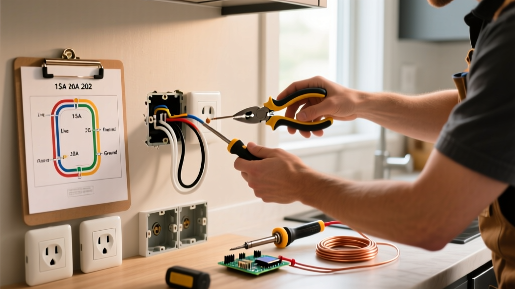
Using needle-nose pliers, bend the stripped copper into a tight "J" or fishhook shape. Critical Rule: The hook must face clockwise. When you tighten the terminal screw (which turns clockwise), the screw will pull the wire loop tighter around the shaft. A counter-clockwise loop will be pushed out from under the screw head as you tighten it.
Step 4: Terminate and Torque
- Ground First: Hook the bare copper wire around the green grounding screw.
- Neutral Second: Hook the white wire around the silver terminal screw.
- Hot Last: Hook the black wire around the brass terminal screw.
Tighten each screw firmly. Modern NEC guidelines require terminals to be tightened to the manufacturer's listed torque. For most 15A and 20A residential receptacles, this is 14 in-lbs. Using a calibrated torque screwdriver ensures the connection won't loosen from thermal cycling.
Step 5: Fold and Mount
Carefully fold the wires into the electrical box using a "Z" or accordion fold. Do not simply shove them in, which can pinch the hot wire against the metal box or disconnect a wire nut. Align the yoke with the box, drive the mounting screws, and attach the faceplate. Ensure the faceplate sits flush; if the box is recessed, use a plastic receptacle spacer (extender ring) to prevent the yoke from flexing when plugs are inserted.
⚠️ Safety Warning: Multi-Wire Branch Circuits (MWBC)
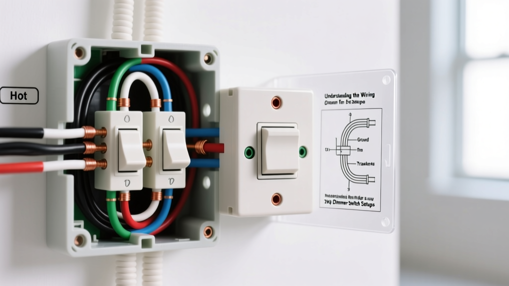
If you see a red wire and a black wire connected to the brass screws of your old outlet (with the break-off tab removed), you have an MWBC. You must turn off both corresponding breakers (or the double-pole breaker) before working on this circuit, or you risk a fatal 240V shock from the shared neutral.
Troubleshooting Common Failure Modes
- Outlet feels warm to the touch: Usually caused by a loose terminal screw or a daisy-chained backstab connection. Turn off power immediately, re-terminate using side screws, and check for scorch marks on the yoke.
- Plugs fall out easily: The internal brass contact wipers inside the receptacle slots have lost their tension. This is common in older, non-TR outlets. The only fix is complete replacement; do not attempt to bend the internal contacts.
- Breaker trips instantly upon plugging in a device: Check for a "ground fault" where a stray strand of bare copper is touching the metal electrical box or the silver/brass terminal screws. Ensure the bare ground wire is pushed deep into the back of the box.
Final Thoughts on Outlet Anatomy
Mastering the parts of an electrical outlet transforms a daunting electrical task into a straightforward mechanical process. By prioritizing side-wire terminations, respecting torque specifications, and utilizing Tamper-Resistant models, you ensure your home's electrical infrastructure remains safe, durable, and fully compliant with 2026 safety standards.