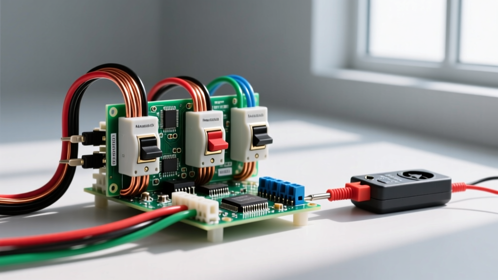
Understanding the NPN Switch and Relay Interface
An NPN switch operates by completing the path to ground (0V). When the NPN transistor turns on, it "sinks" current from the load back to the negative supply rail. In a typical 24V DC industrial control panel, the relay module is wired in two distinct halves: the coil side (control) and the contact side (load).
Coil Side Wiring (The Control Circuit)
The coil side is the low-voltage input. For an NPN-triggered relay module, the positive supply (e.g., +24V DC) is wired directly to one side of the relay coil. The other side of the coil is wired to the collector of the NPN switch. When the NPN switch activates, it pulls this line to ground, completing the circuit and energizing the coil. Because the NPN switch handles the ground path, the control logic is often referred to as "sinking" the coil current.
Contact Side Wiring (The Load Circuit)
The contact side is completely electrically isolated from the coil side via the relay's internal magnetic field. The common (COM) terminal receives the high-power source (e.g., 120V AC or 48V DC). The Normally Open (NO) or Normally Closed (NC) terminal routes power to your load. When the NPN switch energizes the coil, the armature pulls in, bridging COM and NO to power the load.
Load Selection Decision Path and Rating Table
The most common mistake makers and junior technicians make is looking only at the "10A at 250V AC" rating printed on the relay cover. That rating assumes a purely resistive AC load. If you are switching a DC motor or a solenoid, that rating is dangerously optimistic. Below is the master rating table for a standard industrial 24V DC coil relay module.
| Parameter | Specification | Notes & Constraints |
|---|---|---|
| Coil Voltage | 24V DC (±10%) | Must match PSU; undervoltage causes contact chatter. |
| Coil Resistance | 1,440 Ω | Draws approx. 16.6 mA; easily driven by most NPN sensors. |
| Contact Rating (Resistive AC) | 10A @ 250V AC | Only applies to heaters, incandescent lamps, or resistors. |
| Contact Rating (Resistive DC) | 10A @ 28V DC | DC lacks zero-crossing; arcs sustain longer than AC. |
| Making Capacity | 30A (for 20ms) | Handles brief inrush currents of incandescent or capacitive loads. |
| Breaking Capacity (Inductive) | 3A @ 250V AC / 2A @ 28V DC | The governing limit for solenoids, contactor coils, and valves. |
Decision Tree: Which Rating Column Governs Your Load?
To select the right relay, identify your load type. The governing column is the one that accounts for the worst-case arcing or inrush event during switching.
| Load Type | Examples | Governing Rating Column | Selection Rule / Derating |
|---|---|---|---|
| Resistive | Space heaters, power resistors | Resistive AC/DC Rating | Use 80% of the max rating for continuous 24/7 operation. |
| Inductive | Solenoids, relays, transformers | Breaking Capacity (Inductive) | Inductive kickback sustains arcs. Derate standard AC rating by 70%. Use the specific inductive breaking capacity column. |
| Motor (AC) | Fans, pumps, compressors | Motor FLA / HP Rating | Locked Rotor Amperage (LRA) is 6x-8x FLA. The relay must have a specific HP rating; otherwise, derate to 1/6th of the resistive rating. |
| Capacitive | LED drivers, switching supplies | Making Capacity | Inrush can be 50x steady state. Ensure making capacity exceeds peak inrush, or use an NTC thermistor in series. |
Field Testing, Flyback Protection, and Overcurrent Rules
According to Fluke's testing guidelines, a systematic approach to relay diagnostics separates a dead component from a wiring fault. Here is how to test the NPN switch and relay assembly on the bench and in the panel.
How to Test It Dead (Power Off)
- Verify De-energization: Use a non-contact voltage tester and a multimeter to confirm zero voltage on both coil and contact sides.
- Coil Continuity: Place multimeter probes across the coil terminals. A healthy 24V DC coil will read between 1,000 Ω and 1,500 Ω. An "OL" (open loop) reading means the internal copper wire is snapped; a reading near 0 Ω means an internal short.
- Contact Mechanics: Set the meter to continuity mode. Probe COM and NO; it should read "OL". Manually press the relay armature with a non-conductive tool (like a plastic spudger). The meter should beep, indicating a clean mechanical bridge.
How to Test It Live (Power On)
- Coil Voltage: Trigger the NPN switch. Measure DC voltage directly across the coil terminals. It must read within 10% of nominal (21.6V to 26.4V). If it reads 14V, your NPN switch is dropping too much voltage or your wire gauge is too thin.
- Contact Voltage Drop: With the relay energized and the load running, measure the AC or DC voltage across the COM and NO terminals. A healthy contact will show less than 50mV. If you read 2V or more, the contacts are pitted or carbon-fouled and are burning up power as heat.
When to Repair vs. Replace
In modern industrial and DIY contexts, always replace a failing electromechanical relay. Older practices involved filing down pitted silver-alloy contacts, but this removes the factory-applied anti-welding coating and alters the contact gap, leading to unpredictable failure. If your live test shows high voltage drop across closed contacts, or if the NPN switch is getting hot to the touch (indicating it is absorbing flyback energy due to a missing diode), swap the relay module immediately. For socketed relays, pull the relay from the base; for PCB-mounted modules, desolder or replace the entire module block.
Overcurrent Protection: Fuses vs. Breakers
Never treat fuses and breakers as interchangeable for relay contact protection. A standard thermal-magnetic breaker has a slow time-current curve designed for wire protection; during a dead short, a 10A breaker may let 100A+ flow for 100ms before tripping. That I²t let-through energy will easily vaporize a 10A relay contact. To protect the relay contacts, use a fast-acting fuse (like a Mersen Class CC or gG type) on the load side. The fuse's rapid clearing time limits the let-through current, saving the relay contacts from welding shut during a catastrophic load fault.
Frequently Asked Questions
What is the difference between an NPN switch and a PNP switch?
The core difference lies in what they switch. An NPN switch is a "sinking" device; it connects the load to ground (0V) when activated. A PNP switch is a "sourcing" device; it connects the load to the positive voltage supply when activated. In industrial automation, NPN is the standard in Asia and favored for its short-circuit safety (a grounded short simply blows a fuse without triggering the load), while PNP is dominant in Europe and North America. You cannot wire a PNP sensor to a module designed specifically for NPN inputs without adding an inverting transistor stage.
Can I wire an NPN switch directly to a 120V AC motor?
No. An NPN switch (whether a discrete transistor or a proximity sensor) is a low-voltage DC solid-state device. Applying 120V AC to its output will instantly destroy the semiconductor junction and create a severe shock and fire hazard. The NPN switch must only be wired to the low-voltage DC coil of a relay module. The relay's electrically isolated contacts are then used to switch the 120V AC motor.
Why is my NPN switch relay chattering or buzzing?
Chattering usually indicates insufficient coil voltage or a failing flyback protection circuit. If the NPN switch has a high saturation voltage, or if the wire run from the 24V power supply is too long and thin (causing voltage drop), the coil may receive less than 80% of its nominal voltage. This causes the magnetic field to weaken, allowing the spring to push the armature open, which turns the coil back on, repeating the cycle at 60Hz or 120Hz. Check your coil voltage under load, and ensure your power supply isn't browning out when the coil engages.