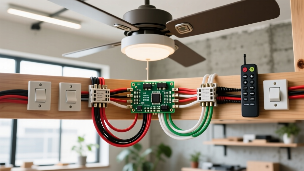
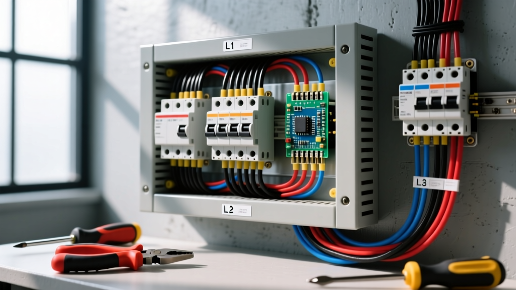
To install an outlet with a switch—technically known as a combination switch/receptacle device—you must first identify the circuit topology. The most common residential application uses a single-gang combo device (like the Leviton 5241 or 5243) to add a switched light fixture to an existing, unswitched outlet box without pulling a new dedicated switch loop. Because you are cramming two distinct functions into one yoke, terminal mapping and wire management are critical to prevent overloading the device or creating a fire hazard.
This procedure involves working inside an active electrical box. Before removing the faceplate, de-energize the circuit at the main service panel or subpanel breaker. Apply a lockout/tagout device if possible. Verify the circuit is dead using a CAT III or CAT IV non-contact voltage tester (NCVT) and a multimeter tested on a known live source. Never rely on a wall switch to isolate power. Local codes (NEC-style guidance) may require a licensed electrician for new circuit extensions; your local AHJ has final authority.
Tools, Materials, and Device Ratings
Using the correct gauge wire and matching device rating is non-negotiable. A 20A breaker requires 12 AWG wire and a 20A rated device; a 15A breaker requires 14 AWG wire and a 15A device. Never install a 15A combo device on a 20A circuit.
- Combo Device: Leviton 5241 (15A, 125V) or Leviton 5243 (20A, 125V). Typical cost: $8–$14.
- Wire: 14/2 NM-B (for 15A circuits) or 12/2 NM-B (for 20A circuits). Solid copper THHN for pigtails.
- Connectors: Wago 221 lever nuts (ideal for tight single-gang boxes) or Ideal wire nuts.
- Testers: Klein Tools NCVT-3 non-contact voltage tester, Fluke 117 True-RMS multimeter.
- Hand Tools: Klein 11055 wire strippers, Phillips #2 screwdriver, torpedo level.
Combo Device Configurations and Specifications
Before stripping wires, determine which configuration you are wiring. The physical break-away tabs on the brass (hot) side of the receptacle dictate how the device behaves. Review the table below to match your physical install to the correct internal wiring logic.
| Configuration | Device Example | Break Tab Status | Wire / Breaker | Primary Use Case |
|---|---|---|---|---|
| Switch controls separate light; outlet always hot | Leviton 5241 | Tab INTACT (Hot feed shared) | 14 AWG / 15A | Adding a closet or vanity light to an existing bedroom/bath outlet |
| Switch controls integrated outlet (entire receptacle) | Leviton 5241 | Tab INTACT (Switched hot feed) | 14 AWG / 15A | Garage or basement tool receptacle that must be physically switched off |
| Half-hot receptacle (top switched, bottom always hot) | Leviton 5241 | Tab BROKEN on brass side | 14 AWG / 15A | Living room lamp control via wall switch while keeping bottom hot for TV |
| 20A Kitchen/Utility combo (Switch controls light) | Leviton 5243 | Tab INTACT (Hot feed shared) | 12 AWG / 20A | Utility room or kitchen counter where 20A small-appliance branch circuit is required |
Source: Device specifications align with Leviton combination device technical data and standard NEMA 5-15R / 5-20R configurations.
Step-by-Step Installation: Switch Controls a Separate Light
The following steps detail the most complex and common scenario: power enters the single-gang box, the receptacle remains always hot, and the switch controls a separate light fixture via a 14/2 or 12/2 NM-B cable run to the ceiling. We will use the pigtail method to ensure secure, code-compliant terminations.
- Prepare the Box and Grounds: Strip 3/4 inch of insulation from all conductors. Gather the bare copper ground wire from the panel feed, the bare copper ground wire going to the light fixture, and a 6-inch bare copper pigtail. Twist them together and secure with a Wago 221 lever nut or wire nut. Terminate the other end of the pigtail to the Green grounding screw on the combo device. Torque to approximately 12-14 in-lbs (snug plus a quarter turn).
- Splice and Land the Neutrals: The switch mechanism on a standard combo device does not require a neutral. Gather the white neutral wire from the panel feed and the white neutral wire going to the light fixture. Splice them together with a 6-inch white pigtail. Terminate the white pigtail to one of the Silver screws on the receptacle side of the device. Cap the unused second silver screw with electrical tape to prevent accidental contact.
- Feed the Receptacle Hot: Take the black (hot) wire from the panel feed. Because this single black wire must feed both the receptacle and the switch, you must create a pigtail splice. Connect the panel black wire to two 6-inch black pigtails using a wire nut. Terminate the first black pigtail to the Brass screw on the receptacle side. Ensure the break-away fin between the two brass screws remains intact.
- Feed the Switch Line: Take the second black pigtail from your previous splice and terminate it to the Brass screw on the switch side of the device. This provides constant line voltage to the switch mechanism.
- Terminate the Switched Load: Take the black wire from the NM-B cable running up to the light fixture. Terminate this wire to the Black (or dark-colored) screw on the switch side. This is your switched load. When the toggle is flipped, power flows from the brass line screw, through the switch mechanism, and out the black load screw to the light.
- Mount and Dress the Box: Carefully fold the wires into the back of the single-gang box. Place the grounds and neutrals deep in the back, and the hot conductors near the front. Mount the device yoke to the box using the provided 6-32 machine screws. Use a torpedo level to ensure the yoke is perfectly plumb before tightening. Install the faceplate.
Verify and Test Procedure
Do not assume the wiring is correct just because the breaker didn't trip upon re-energizing. Follow this verification sequence to ensure safe operation and correct polarity.
- Re-energize: Turn the breaker back on at the panel.
- Receptacle Voltage Check: Set your Fluke 117 (or equivalent True-RMS multimeter) to AC Voltage. Insert the probes into the receptacle slots (Hot to Neutral). You should read 120V ± 5V (acceptable range 114V–126V per ANSI C84.1 standards). Read Hot to Ground; it should also read 120V. Read Neutral to Ground; it should read < 2V. If Neutral-to-Ground reads high, you have a loose neutral connection or a shared neutral overload.
- Switch Load Check: Leave the multimeter probes at the light fixture junction box (or use an NCVT at the fixture). Toggle the switch. The fixture should read 0V when off, and 120V when on.
- Polarity Test: Plug in a standard 3-light receptacle tester. You should see two yellow lights (Correct). If you see a red light (Hot/Neutral reversed), immediately de-energize and check your brass vs. silver screw terminations.
Common Botches and Troubleshooting
Combo devices are notorious for exposing wiring errors that standard single-pole switches hide. If your installation fails, check these three common mistakes.
Botch 1: The Miswired Load (Outlet Only Works When Light is On)
Symptom: The ceiling light turns on, but the receptacle only powers devices when the light is illuminated. When you turn the light off, the outlet dies.
The Fix: You landed the black load wire (going to the light) on the receptacle's brass screw, and the panel feed on the switch's black screw. The switch is now gating power to the entire device. De-energize, remove the device, and ensure the constant panel hot feeds the brass screws, while the light fixture hot lands exclusively on the black/dark switch load screw.
Botch 2: Backstabbing (Push-In) Terminals
Symptom: The device works initially, but after a few months, the receptacle loses power intermittently when plugging in high-draw appliances (like a vacuum), or you smell melting plastic.
The Fix: Never use the push-in backstab holes on a combo device. The internal spring-loaded grips degrade under thermal cycling and high current. According to CPSC electrical safety guidelines, loose connections are a primary cause of residential electrical fires. Always strip the wire to the correct gauge mark and wrap it clockwise around the side-wiring screw terminals.
Botch 3: Forgetting to Break the Tab for a Half-Hot Setup
Symptom: You intended to wire a half-hot receptacle (top switched, bottom always hot) for a living room lamp, but the switch does nothing and both outlets are always live.
The Fix: You failed to snap the break-away fin on the brass (hot) side of the yoke. Use needle-nose pliers to bend the brass tab back and forth until it snaps off. This physically isolates the top brass screw from the bottom brass screw, allowing you to feed constant hot to one and switched hot to the other. (Note: Never break the tab on the silver/neutral side unless you are feeding two completely separate circuits with a shared neutral, which requires a 2-pole breaker and specific NEC multiwire branch circuit compliance).