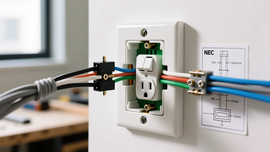
Ground rod wiring connects your home's electrical system to the earth to dissipate high-voltage transients, such as lightning strikes or utility line faults. For a standard 200-amp residential service, the baseline requirement is an 8-foot, 5/8-inch copper-clad steel rod driven into the earth, connected to the main panel's neutral/ground bar using a continuous run of #4 AWG bare copper wire. This setup stabilizes system voltage and provides a safe path for massive electrical surges to dissipate into the soil rather than through your home's framing or appliances.
The Hazard: What Happens Without Proper Ground Rod Wiring
To understand why ground rod wiring is non-negotiable, you have to look at what happens when the utility grid fails. If a 7,200V primary distribution line snaps and falls across your 240V secondary service drop, the voltage on your home's neutral and hot lines spikes to thousands of volts. Without a low-impedance path to the earth, this massive potential seeks ground through your home's internal wiring, plumbing, and structural components, resulting in catastrophic fires or lethal step-potential electrocution for anyone standing nearby.
Lightning presents a similar, albeit faster, hazard. A nearby strike induces massive electromagnetic transients in your service drop. The ground rod wiring acts as a pressure relief valve, shunting this high-frequency, high-voltage energy directly into the soil. Without it, the transient arcs across your panel's bus bars, destroying sensitive electronics, HVAC control boards, and potentially igniting the wooden framing around your service mast.
Ground vs. Bond vs. Neutral: Clearing Up the Confusion
The most common point of failure in DIY electrical work is confusing the grounding electrode (the rod) with the equipment grounding conductor (the bare/green wire in your Romex). They serve entirely different physical functions.
- Neutral (Grounded Conductor): The white wire. This is a current-carrying conductor that provides the normal return path for 120V circuits back to the transformer.
- Bond (Equipment Grounding Conductor): The bare or green wire in your cable. This does not carry current under normal conditions. Its sole job is to connect non-current-carrying metal parts (appliance chassis, panel boxes) back to the panel. If a hot wire touches a metal toaster casing, the bond creates a massive short circuit that instantly trips the breaker.
- Ground (Grounding Electrode System): The ground rod wiring. This connects the entire electrical system to the dirt. It does not trip your breakers during a standard 120V fault. Its purpose is strictly to stabilize voltage to earth and handle high-voltage external surges.
According to the NFPA 70 National Electrical Code (NEC), the grounding electrode system and the equipment bonding system are bonded together at exactly one point: the main service disconnect. Never bond neutral and ground at a subpanel, or you will create parallel neutral paths that energize your ground rods and plumbing.
Sizing and Installation Steps for Ground Rod Wiring
The NEC (Article 250) provides the framework for grounding electrode conductors (GEC). While these standards represent industry best practices, your local Authority Having Jurisdiction (AHJ) or municipal inspector has the final legal authority on code compliance in your area.
GEC Sizing Decision Matrix
The size of your ground rod wiring depends on the size of your largest ungrounded service entrance conductor. Refer to NEC Table 250.66 for exact specifications. Below is the standard residential matrix:
| Service Size | Ungrounded Conductor (Copper) | Minimum GEC Size (Copper) | Physical Protection Required? |
|---|---|---|---|
| 100 Amp | #3 or #2 AWG | #8 AWG (if protected) or #6 AWG | Yes, if #8 is exposed to damage |
| 150 Amp | #1 or #1/0 AWG | #6 AWG | No, if run along surface |
| 200 Amp | #2/0 AWG | #4 AWG | No, #4 is robust enough |
| 400 Amp | 600 kcmil | #2/0 AWG | No |
Step-by-Step Installation Procedure
- Locate and Dig: Choose a spot outside, within 2 feet of where the service entrance conductors enter the home, and below the permanent moisture line if possible. Dig a trench 12 to 18 inches deep to the foundation wall to bury the wire and protect it from landscaping damage.
- Drive the Rod: Use a rotary hammer drill with a ground rod driving bit to sink an 8-foot, 5/8-inch copper-clad steel rod (minimum 10 mils copper cladding) until the top is a few inches below grade. If you hit bedrock, you may trench it horizontally at a 30-inch depth or cut it, provided the exposed length meets AHJ approval.
- Attach the Clamp: Use a listed 'acorn' style grounding clamp rated for Direct Burial (DB). Slide it over the rod, insert the stripped end of your #4 AWG bare copper wire, and torque the stainless-steel set screw to the manufacturer's specification (typically 15-20 in-lbs) using a torque screwdriver.
- Run the Conductor: Pull the #4 AWG bare copper wire through the trench to the panel. The wire must be continuous—no splices are allowed in a Grounding Electrode Conductor unless they are made with irreversible compression connectors or exothermic welding.
- Terminate at the Panel: Route the wire into the main panel through a knockout, securing it with a conduit hub or clamp. Terminate the wire under a dedicated grounding lug or directly into the neutral/ground bar, torquing to the panel manufacturer's specs.
Verification: How to Test Earth Ground Resistance
A critical misconception is that a standard $10 receptacle tester verifies your ground rod wiring. It does not. A receptacle tester only checks the continuity of the equipment bonding jumper back to the panel. It tells you absolutely nothing about the resistance of the dirt surrounding your ground rod.
To properly verify ground rod wiring, you must measure earth resistance. The NEC (Section 250.56) requires a single rod to have a resistance to ground of 25 ohms or less. If it exceeds 25 ohms, you must drive a second rod at least 6 feet away and bond them together.
Testing Methods:
- 3-Point Fall of Potential: The gold standard. Requires driving two auxiliary test spikes into the dirt 20 and 40 feet away and using a dedicated earth ground tester (like the Kyoritsu 4105A, approx. $400). This measures the exact ohmic resistance of the soil-to-rod interface.
- Clamp-On Ground Tester: Devices like the Fluke 1630-2 FC ($1,600+) clamp directly over the ground rod wiring. They induce a voltage and measure the resulting current to calculate resistance without auxiliary spikes. This only works if your ground rod is bonded to a multi-grounded utility neutral or a secondary parallel ground path.
When to call a licensed electrician: If you are upgrading your service panel, replacing a mast, or if your local utility requires a formal grounding certification before releasing the meter seal, hire a professional. Service entrance modifications carry arc-flash risks and require utility coordination.
Ground Rod Wiring FAQ
How deep does a ground rod need to be buried?
The rod itself must be driven at least 8 feet into the earth to ensure it reaches permanent moisture levels, which are critical for maintaining low soil resistance. The ground rod wiring connecting the rod to the panel should be buried in a trench at least 12 inches deep to protect it from shovels, aerators, and frost heave. The connection clamp at the top of the rod should be buried below grade or enclosed in a protective ground rod access cover to prevent corrosion and physical damage.
Can I use a water pipe instead of ground rod wiring?
You can use a continuous underground metal water pipe as a grounding electrode, and the NEC actually requires you to bond it to your system if it is in direct contact with the earth for 10 feet or more. However, you cannot use it as your sole grounding electrode. Because modern plumbing repairs often swap copper for PEX (plastic), a water pipe ground can be unknowingly broken, leaving your home unprotected. You must supplement a metal water pipe ground with a ground rod or a Ufer (concrete-encased) electrode.
Why does my ground rod wiring need two rods?
You only legally need a second rod if the first rod fails to achieve a resistance of 25 ohms or less to the earth. Because testing requires expensive equipment, most electricians and local AHJs adopt a practical shortcut: they simply drive two rods by default, spaced at least 6 feet apart. This preemptively satisfies the 25-ohm rule in almost all soil types without requiring the contractor to perform a formal fall-of-potential test.
Does ground rod wiring prevent my breakers from tripping?
No. This is a fundamental misunderstanding of electrical physics. Your circuit breakers trip because of the equipment bonding conductor (the bare wire in your Romex), which creates a low-impedance short circuit back to the panel when a hot wire touches metal. The earth itself has too much resistance (often 10 to 50 ohms) to allow enough fault current to flow to trip a 20-amp breaker. Ground rod wiring is strictly for high-voltage surge dissipation and system voltage stabilization, not for clearing standard 120V/240V line-to-ground faults. For comprehensive safety frameworks, refer to the ECMweb Grounding and Bonding Guide.