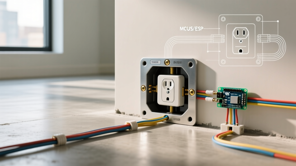
Mounting an electrical panel is the structural securing of a load center enclosure to building framing using rated backing materials and fasteners to support the enclosure's dynamic weight while maintaining strict NEC working-space clearances. Proper mounting dictates the physical stability, thermal dissipation, and legal compliance of your entire electrical distribution system. Beginners frequently confuse mounting the metal enclosure (a structural carpentry task) with installing the internal busbar and breakers (an electrical task), or they mistakenly assume drywall alone can support a loaded 200-amp service.
The Structural Physics of Panel Enclosures
An electrical panel is not a static, lightweight box. Once fully dressed with copper conductors, steel conduit, and breakers, it becomes a heavy, dynamic assembly. The structural theory of mounting focuses on managing both static load (the sheer weight of the materials) and dynamic load (the physical force applied when an electrician pulls stiff wire through knockouts or forcefully resets a tripped breaker).
What changes in a real installation when mounting is done correctly? A rigidly mounted panel ensures that the internal busbar stabs do not flex when breakers are pushed in, preventing arcing and thermal degradation. It also ensures the enclosure remains grounded and bonded to the building structure, aiding in fault current dissipation.
Worked Numeric Example: Fastener Withdrawal Load
Let's calculate the required fastener strength for a standard residential 200-amp, 42-circuit surface-mount panel.
- Static Load: 35 lb (empty steel enclosure) + 30 lb (copper THHN conductors) + 20 lb (EMT conduit and fittings) = 85 lbs total static weight.
- Dynamic Pull Factor: When yanking a stuck 10 AWG wire through a conduit nipple, the momentary pull force can easily triple the static load. We apply a 3.0x safety multiplier: 85 lbs × 3.0 = 255 lbs design load.
- Fastener Selection: We use four 1/4" x 3" structural lag screws (such as the Simpson Strong-Tie SDWS) driven into Douglas Fir-Larch wall studs.
- Withdrawal Capacity: According to structural timber data, a 1/4" lag screw yields approximately 250 lbs of withdrawal capacity per inch of thread engagement. Assuming the screw passes through 1/2" drywall and 1/2" enclosure steel, we have 1.5" of thread biting into the wood stud.
- Calculation: 1.5" × 250 lbs/inch = 375 lbs per screw. Four screws yield a total withdrawal capacity of 1,500 lbs.
With a 1,500 lb capacity against a 255 lb design load, the mounting assembly provides a massive safety margin, ensuring the panel will never pull away from the wall during aggressive wire pulling.
NEC 110.26 Working Space and Mounting Clearances
Mounting location is not solely dictated by where the studs are conveniently spaced; it is strictly governed by the 3D volume of space required in front of the enclosure. The National Electrical Code (NEC) Article 110.26 mandates specific working spaces to ensure an electrician can safely operate, troubleshoot, and escape in the event of an arc flash. For a deeper dive into these legal requirements, refer to the NFPA 70 National Electrical Code or Mike Holt's NEC 110.26 working space summaries.
| Parameter / Voltage to Ground | Condition 1 (Exposed live parts on one side only) | Condition 2 (Exposed live parts on both sides of workspace) | Condition 3 (Exposed live parts on both sides, with insulating barriers) |
|---|---|---|---|
| 0 to 150 Volts | 3 Feet | 3 Feet | 3 Feet |
| 151 to 600 Volts | 3 Feet | 4 Feet | 4 Feet |
| Minimum Workspace Width | 30 inches, or the width of the equipment, whichever is greater | ||
| Minimum Headroom | 6.5 feet (2.0 m) from the floor to the top of the workspace | ||
| Door Swing Clearance | Panel doors must be capable of opening to at least 90 degrees | ||
Condition 1 is the standard for most residential and light commercial walls where the panel is mounted flat against a single wall. Condition 2 applies if you mount the panel in a narrow hallway or closet where another electrical cabinet or grounded metal pipe is directly across from it, requiring a deeper 4-foot setback for higher voltages.
Where You Meet Mounting Theory in Practice
The theory of load distribution and clearances translates into specific carpentry and masonry techniques on the jobsite. The mounting approach changes drastically depending on the wall construction and the enclosure type (flush vs. surface).
Flush-Mounting in Wood Framing
Flush-mounting a panel between standard 16-inch on-center (OC) wall studs requires structural framing modifications. A standard 14-inch wide panel will not fit between 14.5-inch rough stud bays once you account for drywall and wire routing. You must cut the stud and install a structural header and cripple studs (trimmers) to transfer the roof/floor load around the enclosure. Never simply notch a load-bearing stud to slide a panel in; this compromises the building's structural integrity and violates building codes.
Surface-Mounting on Masonry and CMU
Mounting directly to concrete masonry units (CMU) or cinder block using standard Tapcon screws is a common failure point. The vibration of slamming a heavy breaker handle, combined with the dynamic pull of conduit, can strip the masonry threads over time.
For commercial environments, Unistrut (P1000 series) channels are often anchored to the block wall, and the panel is bolted to the Unistrut using spring nuts. This allows for micro-adjustments during leveling and provides an incredibly rigid, vibration-proof mount.
Thermal Expansion and Material Compatibility
When mounting outdoor enclosures (NEMA 3R or 4) to metal siding or steel framing, you must account for thermal expansion. Steel enclosures and steel framing expand at similar rates, but if you mount an aluminum enclosure to a steel stud wall in a high-heat environment (like an unventilated attic or desert exterior wall), the differing coefficients of thermal expansion can cause fasteners to bind or the enclosure to warp. Always use isolation washers and slotted mounting holes where differential expansion is expected.
Frequently Asked Questions
Can I mount an electrical panel on drywall alone using toggle bolts?
No. While heavy-duty toggle bolts (like Snaptoggles) can hold the static weight of an empty panel, they will fail under dynamic load. The sheer force of pulling stiff copper wire through a knockout, or the physical leverage applied when pushing a breaker onto the busbar, will easily snap toggle bolts or crush the drywall core. The enclosure must be fastened directly to wood studs, metal studs, or masonry.
What is the legal mounting height for a residential panel?
The NEC does not specify a strict height for the bottom or top of the enclosure itself. However, NEC 240.24(A) dictates that the center of the grip of the highest circuit breaker handle cannot exceed 6 feet 7 inches (2.0 meters) above the floor or working platform. When planning your mount, measure the height of your specific panel, locate the top breaker position, and ensure that specific point stays under the 6'7" limit while maintaining the 6.5-foot headroom clearance in front of it.
Do I need to bond the panel enclosure to the grounding system if it's mounted to wood?
Yes. The physical mounting material (wood, drywall, or even painted masonry) acts as an insulator. The metal enclosure must be bonded to the equipment grounding conductor (EGC) or the grounded service conductor (at the main disconnect only) via the internal grounding busbar. You cannot rely on the mounting screws to provide a ground path, as paint, powder coating, and anodizing on the enclosure will break electrical continuity.