
Translating Visual Animations into Code-Compliant Testing
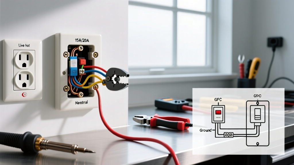
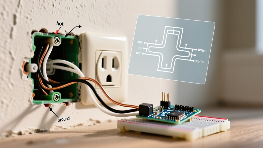
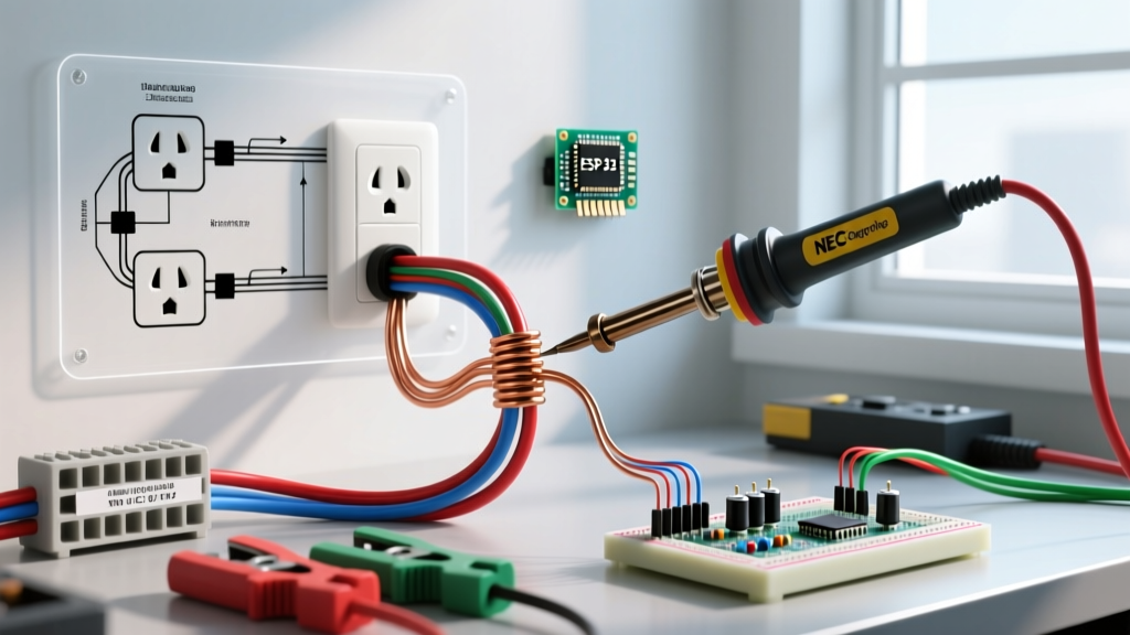
When learning how to wire or troubleshoot a receptacle, many DIYers and apprentice electricians turn to a quick electrical outlet gif or animated diagram to visualize current flow, polarity, or GFCI tripping mechanisms. While these visual aids are excellent for grasping basic concepts—like how a hot wire connects to the brass screw or how a ground fault creates an imbalance—they lack the rigorous, quantitative data required for actual field inspection. Relying solely on visual animations can lead to missed edge cases, such as bootleg grounds or high-resistance neutral connections, which are leading causes of electrical fires.
This comprehensive inspection and testing guide serves as the technical companion to those visual aids. We will break down the exact testing sequences typically depicted in animated guides, translating them into actionable, NEC-compliant inspection protocols using professional-grade testing equipment. Whether you are inspecting a standard NEMA 5-15R duplex receptacle or a complex Multi-Wire Branch Circuit (MWBC), this guide provides the depth required for 2026 electrical standards.
The Limits of Visual Animations in Outlet Testing
Animated diagrams often show a simple closed loop where current flows from the hot terminal, through a load, and returns via the neutral. However, real-world AC circuits involve impedance, voltage drop, and strict grounding requirements mandated by the NFPA 70 National Electrical Code (NEC). A visual animation cannot show you that a neutral wire is carrying 105 volts instead of 120 volts due to a loose connection at the panel, nor can it reveal a 'bootleg ground' where a previous owner illegally jumpered the neutral and ground terminals to trick a basic plug-in tester.
Safety Warning: Never rely on the 'lights' of a cheap $10 plug-in receptacle tester as your sole verification method. These devices can indicate 'Correct' even when a bootleg ground is present or when the neutral is floating under no-load conditions. Always verify with a digital multimeter or a solenoid voltage tester before touching bare conductors.
Step-by-Step Receptacle Testing Sequences
Let us break down the standard testing sequences often simplified in visual guides, applying real-world multimeter diagnostics and specific failure mode analysis.
1. Standard 15A/20A Duplex Receptacle Polarity & Voltage
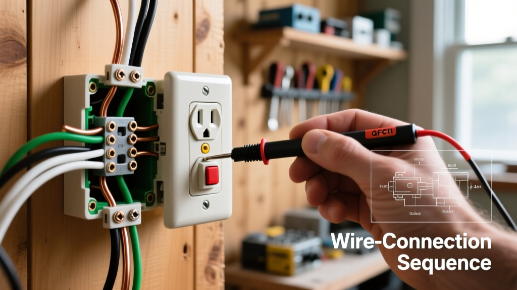
The most common animation shows a plug-in tester lighting up with two yellow LEDs to indicate 'Correct'. To verify this electrically, you must perform a three-point voltage test using a True-RMS digital multimeter, such as the Fluke 117 (retailing around $215). Set your meter to AC Voltage (V~) and take the following measurements at the receptacle slots:
- Hot to Neutral (Short slot to Long slot): Should read between 114V and 126V. If it reads significantly lower (e.g., 105V), you have excessive voltage drop, indicating a loose connection upstream or an undersized wire for the circuit length.
- Hot to Ground (Short slot to U-shaped pin): Should read identical to Hot-Neutral (within 1V). If this reads 0V but Hot-Neutral reads 120V, you have an open ground. If it reads slightly higher than Hot-Neutral, you may have a reversed polarity or a shared neutral issue.
- Neutral to Ground (Long slot to U-shaped pin): This is the most critical diagnostic reading. It should read as close to 0V as possible (typically under 1.5V). A reading of 2V to 5V indicates a loaded neutral with high resistance (a loose neutral wire somewhere on the circuit). A reading of 120V indicates a completely open neutral upstream.
2. GFCI Load vs. Line Wiring Verification
Visual guides frequently animate the internal sensing coil of a Ground Fault Circuit Interrupter (GFCI) detecting a 5mA imbalance and tripping the contacts. However, the most common installation error in 2026 is reversing the LINE and LOAD terminals. According to the Consumer Product Safety Commission (CPSC), a GFCI wired backward will still power the receptacle and may even trip when the internal 'Test' button is pressed, but it will not provide ground-fault protection to the user.
The Diagnostic Procedure:
- Identify the LINE (incoming power) and LOAD (downstream protection) terminals on the back of the GFCI (e.g., Leviton SmartlockPro T5280).
- Use a non-contact voltage tester or multimeter to identify the incoming hot wire before connecting the device.
- Once installed, use an advanced GFCI tester like the Klein Tools RT250 ($38). Unlike older testers that simply short hot-to-ground to simulate a fault, the RT250 injects a precise 6mA test pulse. If the GFCI is wired correctly, it will trip within 25 milliseconds.
- Edge Case Failure: If the RT250 indicates a 'Wiring Fault' or fails to trip the GFCI, but the receptacle has power, the LINE and LOAD wires are almost certainly reversed. Disconnect power, swap the wire sets, and retest.
Diagnostic Matrix: Visual Clues vs. Multimeter Readings
The following matrix translates common visual symptoms (often depicted in troubleshooting animations) into exact multimeter readings and corrective actions.
| Visual Symptom / Animation | Probable Fault Condition | Hot-Neutral Reading | Neutral-Ground Reading | Corrective Action Required |
|---|---|---|---|---|
| Appliance plugs in, no power; Tester shows 'Open Hot' | Tripped breaker, loose pigtail, or broken conductor upstream. | 0V | 0V | Trace circuit to panel; check for tripped AFCI/GFCI upstream or loose wire nut. |
| Lights flicker when appliance turns on; Tester shows 'Correct' | High-resistance neutral connection (loose terminal screw). | 105V - 115V (under load) | 3V - 10V (under load) | Inspect all neutral connections on the circuit; torque terminal screws to manufacturer specs. |
| Tester shows 'Open Ground' but U-pin is physically connected | Broken ground wire upstream or drywall screw piercing the ground conductor. | 120V | 120V | Perform continuity test on ground wire back to panel; inspect cable runs for physical damage. |
| Tester shows 'Correct' but GFCI won't trip on test | Bootleg ground (Neutral jumpered to Ground) masking an open ground. | 120V | 0V (False positive) | Remove receptacle; inspect for illegal jumper wire between silver and green screws. |
Advanced Inspection: Multi-Wire Branch Circuits (MWBC)
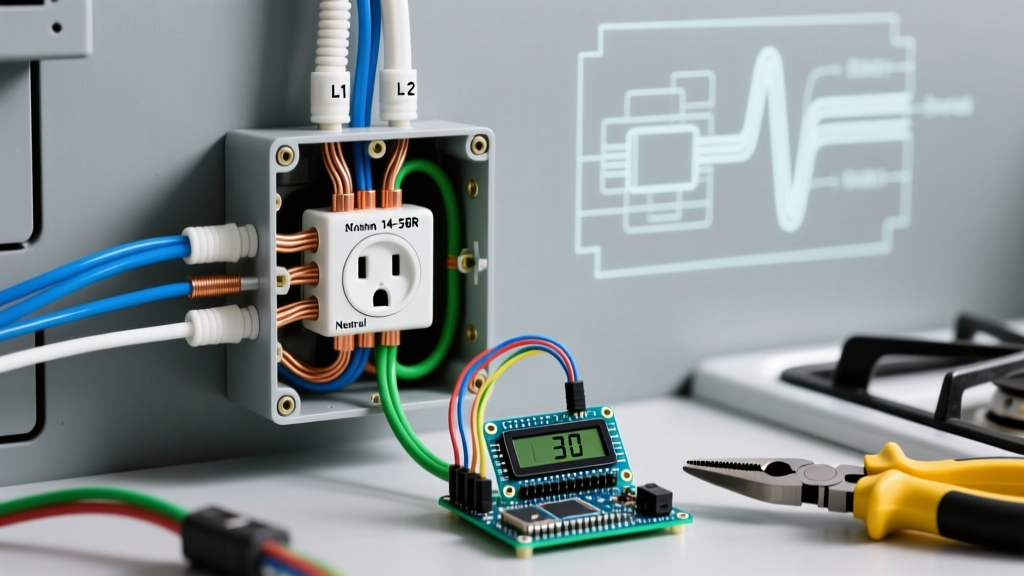
Visual animations rarely cover the complexities of Multi-Wire Branch Circuits, which share a single neutral wire between two hot legs (Phase A and Phase B). In residential panels, this provides 240V across the two hots, but 120V from each hot to the shared neutral. If an MWBC is improperly serviced or the handle tie is missing, OSHA electrical safety standards and the NEC warn of severe shock hazards and neutral overloading.
Inspection Protocol for MWBC Outlets:
- Breaker Verification: Open the panel and verify that the two breakers feeding the circuit are on opposite phases (adjacent breakers in most modern panels like Square D Homeline) and are secured with a listed handle tie or a 2-pole breaker as required by NEC 210.4(B).
- Voltage Cross-Check: At the receptacle, if you are testing a split-wired duplex (where the top half is on one circuit and the bottom half is on another, achieved by breaking the brass tab), measure Hot-Top to Hot-Bottom. It must read 240V. If it reads 0V, both hots are on the same phase, which will cause the shared neutral to carry the sum of both currents, leading to a potential neutral fire.
- Tab Inspection: Physically remove the receptacle and verify that the brass (hot) side break-off tab is completely removed, while the silver (neutral) side tab remains intact.
Recommended Testing Equipment for 2026
To move beyond basic visual guides and perform professional-grade inspections, invest in the following diagnostic tools:
- Fluke 117 True RMS Multimeter ($215): Essential for accurate voltage readings, especially on circuits with non-linear loads (like LED drivers or smart home hubs) that distort the sine wave. Features VoltAlert for non-contact voltage detection.
- Klein Tools RT250 GFCI Receptacle Tester ($38): The industry standard for verifying GFCI trip times and wiring polarity. Features a clear LCD screen that spells out exact fault conditions rather than relying on ambiguous LED light patterns.
- Klein Tools 60107 Torque Screwdriver Set ($65): NEC 110.14(D) mandates that electrical connections be torqued to the manufacturer's specifications. Most standard 15A/20A receptacles (like the Leviton T5280) require 12 to 14 inch-pounds of torque on the terminal screws to prevent thermal expansion and contraction from loosening the wires over time.
FAQ: Visual Troubleshooting & Code Compliance
Can I rely on a smart receptacle's self-testing feature instead of manual testing?
Modern smart GFCIs (introduced in recent NEC cycles) feature automatic self-testing that periodically checks the internal fault-detection circuitry. However, this self-test does not verify that the external wiring (line/load, ground integrity) is correct. You must still perform a manual multi-point voltage test and a physical trip test upon installation.
Why does my plug-in tester show 'Hot/Neutral Reversed' when the power is off?
If a tester indicates reversed polarity or open hot when the circuit is de-energized, you are likely dealing with phantom voltage induced by adjacent live wires running in the same conduit or cable bundle. Use a low-impedance (LoZ) setting on your multimeter to bleed off phantom voltage and get a true reading.
Are push-in backwire connectors safe for permanent installations?
While many visual guides show wires being pushed into the back of a receptacle for speed, standard push-in (stab-in) connections on 14 AWG wire are notorious for high-resistance failures over time due to thermal cycling. For 2026 best practices, always use the side-terminal screws or, if available, the screw-clamp backwire mechanism, which provides a much larger surface area and secure mechanical grip, torqued to the manufacturer's specification.