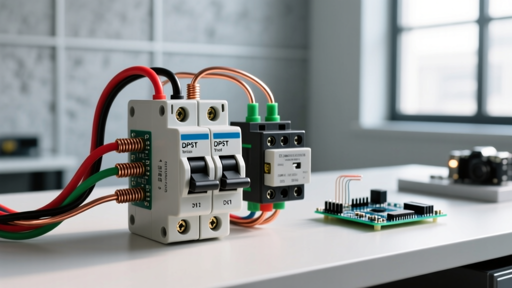

A double pole single throw (DPST) switch connects or disconnects two independent circuits simultaneously with a single actuator. If you need to manually isolate a 240V resistive load like a baseboard heater, use a 20A manual DPST toggle switch (default pick: Leviton 1865). If you are automating the switching of a high-current load via a low-voltage control signal, you need an electromechanical DPST contactor (default pick: Eaton C25DND230). Both devices serve the same logical function—two poles, one ON/OFF state—but their internal architecture, rating columns, and wiring rules differ drastically.
Anatomy and the Breaker Distinction
A common and dangerous mistake on the jobsite is treating a DPST switch as an overcurrent protective device. A DPST switch is strictly an isolation or control device. It lacks the thermal-magnetic trip curve of a circuit breaker. While a breaker is engineered to safely interrupt a 10,000A short-circuit fault (10kAIC) by extinguishing the arc in a fraction of a cycle, a standard DPST switch has virtually zero short-circuit breaking capacity. If a dead short occurs downstream of a DPST switch, the switch contacts will weld shut or vaporize unless the circuit is backed by a properly sized fuse or breaker with the correct time-current curve. Always feed your DPST switch from a branch-circuit breaker sized to the wire ampacity and the switch’s continuous rating.
Rating Table: Which Column Governs Your Load?
When reading a DPST datasheet, the 'Amps' printed on the side of the box is usually the resistive rating. If you switch a motor or a transformer with a switch rated only for resistive loads, the inductive inrush will pit the contacts and cause premature failure. Here is how manual switches and electromechanical contactors compare under real-world 2026 pricing and specifications.
| Parameter | Manual DPST (Leviton 1865) | DPST Contactor (Eaton C25DND230) |
|---|---|---|
| Coil Voltage | N/A (Manual Actuator) | 240V AC (Options: 24V, 120V, 24VDC) |
| Contact Rating (Resistive) | 20A @ 120/277V AC | 30A @ 240V AC |
| Contact Rating (Motor/Inductive) | 2 HP @ 240V AC | 30A FLA / 150A LRA (Definite Purpose) |
| Breaking Capacity (Short Circuit) | Requires upstream breaker | Requires upstream breaker (Not fault-rated) |
| Mechanical Life | ~50,000 operations | ~1,000,000 operations |
| Approx. Cost (2026) | $15 - $20 | $28 - $35 |
Which rating column governs? For heating elements and incandescent lighting, use the Resistive column. For compressors, fans, or pumps, you must use the Motor FLA (Full Load Amps) and LRA (Locked Rotor Amps) columns. According to NFPA 70 (NEC) Article 430, a motor disconnect must have an ampacity rating of at least 115% of the motor's FLA. If your motor draws 18A FLA, a 20A manual switch is illegal and unsafe; you must step up to a 30A contactor or a heavy-duty 30A safety switch.
Wiring the Coil vs. the Contacts (and Flyback Protection)
With a manual DPST switch, wiring is straightforward: line in, load out. But with a DPST contactor, you are dealing with two entirely isolated circuits: the control circuit (coil) and the load circuit (contacts).
Load Side (Contacts): Wire your L1 and L2 line voltage to the top terminals (usually labeled 1 and 3, or L1 and L2), and your load to the bottom terminals (2 and 4, or T1 and T2). For 10 AWG THHN copper, torque the terminal screws to 14 in-lbs to prevent thermal loosening over time.
Control Side (Coil): Wire your control voltage to the A1 and A2 terminals. If you are switching a DC coil (e.g., a 24VDC contactor driven by an ESP32 relay module or PLC), you must install a flyback diode (like a 1N4007) in reverse bias across A1 and A2. When the coil de-energizes, the collapsing magnetic field generates a high-voltage spike that will fry your microcontroller's output transistor. The diode safely recirculates this kickback current. For AC coils, use an RC snubber network or a metal oxide varistor (MOV) across the coil to suppress arcing on the physical control switch that triggers the contactor.
How to Test a DPST Switch: Dead and Live Checks
Troubleshooting a DPST device requires verifying both mechanical continuity and electrical integrity under load. Assume 75°C insulation ratings and 30°C ambient temperature for standard baseline testing.
1. The Dead Test (Continuity)
With the breaker OFF and verified dead, set your multimeter to the Ohms (Ω) or continuity setting. Place probes across L1 and T1. Toggle the switch or manually depress the contactor armature. You should read < 1.0 ohm. Repeat for L2 and T2. If you read infinite resistance (OL) when closed, the internal linkage is broken. If you read > 5 ohms when closed, the contacts are heavily pitted or carbon-fouled.
2. The Live Test (Voltage Drop)
Continuity tests miss high-resistance faults that only manifest under heavy current. With the circuit energized and the load running at full draw, set your multimeter to AC Volts. Place one probe on the line terminal (L1) and the other on the corresponding load terminal (T1). You are measuring the voltage drop across the closed switch contacts. A healthy switch will drop less than 50 millivolts (0.050V). If you read 2V or more, the contacts are degrading and generating dangerous heat. (Reference: Eaton Definite Purpose Contactors Catalog specifies maximum millivolt drops for acceptance testing).
Repair vs. Replace: When to Swap the Component
There is exactly one correct answer for electromechanical switches and contactors in the field: Replace, never repair.
In the mid-20th century, technicians would file down pitted copper contacts to extend their life. Modern DPST contacts are made of silver-cadmium oxide or silver-nickel alloys, often plated only microns thick. Filing them removes the anti-welding alloy layer, guaranteeing that the next time the switch opens under an inductive load, the resulting arc will melt the contacts together. Furthermore, if a contactor coil shows signs of melting, darkening, or reads open on an ohmmeter, the coil insulation has failed. A replacement Eaton C25DND230 costs $30; a melted contactor causing an electrical fire costs thousands. Treat them as consumable wear items.
The DPST Selection Decision Tree
Use this decision path to select the exact component for your workbench or jobsite. Do not guess based on physical size.
| Condition / Requirement | Decision Path | Concrete Pick |
|---|---|---|
| Need a manual wall disconnect for a 240V baseboard heater (under 20A)? | Manual DPST, Resistive Rating governs. | Leviton 1865 (20A, 120/277V) |
| Need to automate a 240V HVAC compressor via a 24VAC thermostat signal? | DPST Contactor, Motor LRA/FLA governs. 24VAC coil. | Eaton C25DND230 (30A DP, 240V load / 24V coil) |
| Switching a 3-phase motor? (Wait, DPST is only 2-pole!) | STOP. You need a 3-Pole (TPST) contactor or safety switch. | Schneider TeSys LC1D09 (3-Pole) |
| Switching a low-voltage DC load (e.g., 12V 40A solar bank)? | AC ratings do NOT apply to DC. DC arcs do not self-extinguish. | Blue Sea Systems 6006 (e-Series DPST, DC rated) |
| Need to switch a 5A 120VAC signal via an ESP32 GPIO pin? | Use a 5VDC coil DPST relay, add 1N4007 flyback diode. | Omron G2R-2-S DC5 (DPDT/DPST relay module) |
The Default Recommendation: If you are building a home automation panel to control heavy 240V resistive or light inductive loads (up to 30A) using a smart relay or microcontroller, standardizing on the Eaton C25DND230 (or its 120V coil equivalent, the C25DND130) is the most reliable, cost-effective path. It provides robust silver-alloy contacts, clear terminal markings, and a mechanical life that will outlast the smart-home controller driving it. Just remember to pair it with a correctly sized 2-pole branch breaker and respect the flyback diode rule on the control side.