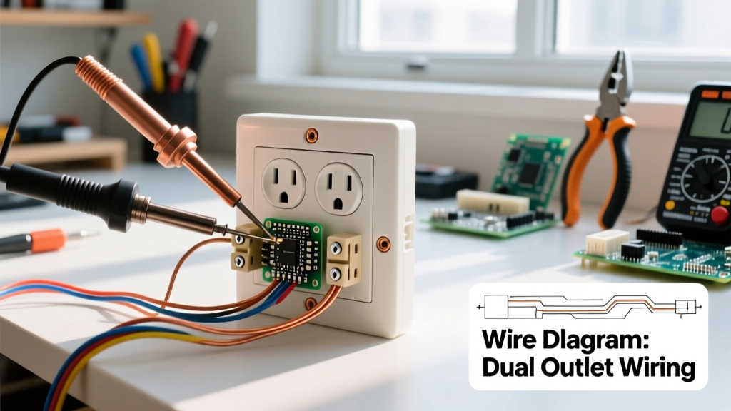
The fundamental circuit symbol for a wire is a solid, straight black line connecting two component nodes. When wires intersect and connect, a solid junction dot is required. If they cross without connecting, modern standards dictate a simple cross with no dot or a 'hop-over' semicircle. Never assume a physical or schematic connection based on proximity; always verify with a meter.
The Complete Wire Symbol & Color Code Reference Table
While the schematic symbol for a wire remains a simple line globally, the physical insulation color it represents changes drastically depending on your regional electrical code. Use this table to translate schematic lines to real-world bench and jobsite wiring.
| Symbol / Line Type | Schematic Meaning | NEC Color (US/Canada) | IEC Color (EU/UK/AU) | Practical Field Note |
|---|---|---|---|---|
| Solid Straight Line | Standard conductor | Black, Red, Blue (Hot) | Brown, Black, Grey (Line) | Default path for current. Always treat as energized until tested. |
| Line with Junction Dot | Electrical connection | N/A (Splice point) | N/A (Splice point) | Must have a solid dot. No dot means no electrical connection. |
| Line Crossing (No Dot) | Crossing, no connection | N/A | N/A | Modern IEEE standard. Wires pass over/under each other without contacting. |
| Line with Ground Symbol | Equipment grounding | Green, Bare Copper | Green/Yellow Stripe | Safety fault path. Should never carry normal load current. |
| Line with Neutral Symbol | Grounded conductor | White, Grey | Blue (EU), Black (Old UK) | Carries return current. Treat as a live, shock-hazard conductor. |
| Dashed / Dotted Line | Mechanical linkage or shield | N/A | N/A | Do not confuse with signal wires; indicates physical coupling or shielding. |
Regional Standards: NEC vs. IEC vs. Old UK Colors
A schematic might be drawn in Germany but built in Texas. Understanding which standard applies to your region prevents catastrophic miswiring.
- US & Canada (NEC / CEC): Governed by NFPA 70 (National Electrical Code). Ungrounded (hot) conductors are typically black, red, or blue. The grounded (neutral) conductor must be white or grey. Equipment grounding is green or bare.
- EU, Australia, & Modern UK (IEC): Governed by IEC 60445. Line conductors are brown (L1), black (L2), and grey (L3). Neutral is strictly blue. Protective earth is green with a yellow stripe.
- The Old UK Trap (Pre-2004): Before harmonizing with Europe in 2004, the UK used red for live, black for neutral, and green for earth. If you are renovating a pre-2004 British property, a black wire is a live hot, not a neutral. This is one of the most dangerous legacy color codes in the world.
The 'Rows People Get Wrong' Field Notes
Schematics and wire colors look clean on paper, but the jobsite is messy. Here are the specific symbols and color conventions that consistently cause errors:
1. The 'No Dot' Crossing Trap
In pre-1990s schematics, a simple cross (an 'X') often implied a connection. Modern IEEE 315 standards dictate that a cross without a solid junction dot means the wires do not connect. If you are reading a vintage amp or appliance schematic, assume an 'X' is a connection. If you are reading a modern ESP32 or industrial PLC print, assume no dot means no connection. When in doubt, trace the net with a multimeter.
2. The White Wire in a US Switch Loop
In standard US residential wiring, a white wire is neutral. However, in a 2-wire cable running up to a single-pole light switch (a switch loop), the white wire is used as the hot line feeding the switch. The NEC requires this white wire to be re-identified with black tape or paint at both ends. In 40-year-old houses, that tape has usually fallen off. Never assume a white wire in a switch box is safe to touch.
3. Ground vs. Neutral Symbols
On a schematic, the neutral symbol (a line ending in a smaller perpendicular line) and the ground symbol (a line ending in three descending horizontal lines) both ultimately tie to earth at the main service panel. However, neutral carries return load current and will have a voltage drop across it. Ground is strictly for fault clearing. Swapping these on a PCB or in a subpanel will cause GFCI breakers to trip immediately and create shock hazards on appliance chassis.
Safe Interpretation When Markings Are Faded or Missing
When you are troubleshooting a legacy control panel or an old piece of test equipment, schematic labels fade and wire insulation gets painted over. Here is the exact procedure to safely interpret unidentified wires:
- De-energize and LOTO: Turn off the breaker and apply a Lockout/Tagout device.
- Verify Dead: Test your multimeter on a known live source (like a receptacle) to prove the meter works. Then test the target circuit phase-to-phase and phase-to-ground. It must read 0V.
- Continuity Testing: Switch your meter to continuity mode (audible beep). To find a neutral among a bundle of faded white/grey wires, test each wire to the main grounding bus bar. A true neutral will show very low resistance (typically under 1 ohm). A disconnected hot wire will read 'OL' (Open Loop).
- Tone Tracing: For low-voltage control wires where colors have completely faded, use an inductive tone generator and probe. Clip the tone generator to the suspected wire and the ground, then trace the physical path with the wand.
For a deeper guide on using your meter for these checks, reference the Fluke continuity testing guidelines.
Frequently Asked Questions
What is the circuit symbol for a wire crossing without connection?
In modern schematics (post-1990s IEEE/IEC standards), a wire crossing without a connection is represented by two straight lines intersecting with no junction dot. In older schematics, it was represented by a 'hop-over' or 'bridge' symbol, where one line forms a small semicircle over the other. Today, the hop-over is largely deprecated because it can be misread as a component symbol or clutter dense PCB layouts, but you will still see it in vintage audio and automotive wiring diagrams.
How do you represent a shielded wire in a schematic?
A shielded wire is typically drawn as a standard solid straight line for the inner core conductor, surrounded by a dashed or dotted cylindrical line representing the shield. The shield line is then terminated with a standard equipment ground symbol. In RF or high-speed data schematics (like USB or Ethernet), you may also see the shield represented as a separate pin on a connector block, labeled 'SH' or 'Drain', indicating it must be tied to chassis ground at one end only to prevent ground loops.
What does a dashed line around a wire symbol mean?
A dashed or dotted line enclosing a group of wires or components usually indicates a physical boundary rather than an electrical one. It represents a shielded enclosure, a mechanical linkage (like a ganged potentiometer where one physical knob turns two electrical resistors), or a specific functional block (like a sealed relay module). It does not carry current itself.
Is the circuit symbol for wire different for AC and DC?
No, the fundamental circuit symbol for a wire (a solid straight line) is identical for both AC and DC circuits. The difference is indicated by the power source symbol at the origin of the wire, not the wire itself. A DC source is denoted by a long and short parallel line (battery) or a solid line with a dashed line beneath it. An AC source is denoted by a sine wave inside a circle. However, in high-voltage DC (HVDC) transmission schematics, you may see specific polarity markers (+ or -) placed directly adjacent to the wire line to clarify potential.