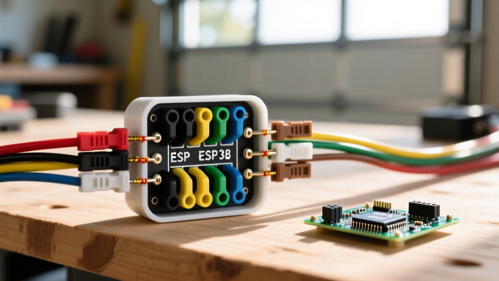
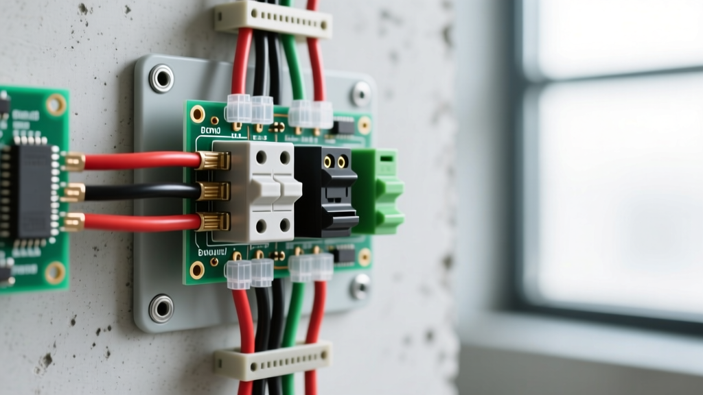
Most DIYers learn 2 switch 1 light wiring using standard residential 3-way toggle switches. But what happens when your 'one light' is a 20-amp bank of LED high-bays in a workshop, a 30A outdoor security array, or a heavy-duty UV curing lamp? Standard 15A or 20A mechanical wall switches will arc, pit, and eventually weld shut under high inrush currents. The professional, code-compliant solution is to wire your two switches to the coil of a lighting contactor, letting the contactor’s heavy-duty contacts handle the actual load.
This guide bridges residential wiring concepts with industrial electromechanical components, showing you exactly how to size, wire, and test a contactor-based 2-switch-1-light circuit.
Contactor Selection: Coil vs. Contact Ratings
When adapting 2 switch 1 light wiring for heavy loads, the wall switches only carry the tiny current required to energize the contactor's electromagnet (the coil). The contactor's internal power contacts carry the actual lighting load. Selecting the wrong contactor is the most common cause of premature failure in high-wattage DIY builds.
Which Rating Column Governs Your Load?
Modern LED high-bay lights and fluorescent ballasts do not act like simple resistive heaters. When you flip the switch, the internal drivers draw a massive spike of inrush current to charge their capacitors. Therefore, the Tungsten or Ballast ampacity rating governs your load, not the higher Resistive rating. If your LED array draws 18A continuously but has a high inrush, a contactor rated for 30A Resistive but only 15A Ballast will fail prematurely.
| Model / Class | Coil Voltage (A1-A2) | Resistive Amps | Ballast / Tungsten Amps | Breaking Capacity |
|---|---|---|---|---|
| Schneider 8903L (Lighting) | 120V AC | 30A | 20A | N/A (Not for fault) |
| Eaton C25DNF120 (Def. Purpose) | 120V AC | 40A | 30A | N/A |
| Siemens 3TF46 (IEC General) | 24V DC | 38A (AC-1) | 15A (AC-5a) | 10 kA |
| Bodine 430 (Heavy Duty Relay) | 240V AC | 50A | 40A | N/A |
Wiring the Control (Coil) and Load (Contact) Circuits
A contactor splits your 2 switch 1 light wiring into two entirely separate circuits: the low-current control circuit and the high-current load circuit.
The Control Circuit (Coil Side)
The coil terminals are universally labeled A1 and A2. In a standard maintained 3-way switch setup, your hot feed goes to the common terminal of Switch 1. The two traveler wires run to Switch 2. The common terminal of Switch 2 runs directly to A1 on the contactor. A2 wires directly to the neutral bar. When the switches align to pass voltage, the coil energizes, pulling the contacts shut.
The Load Circuit (Contact Side)
The power contacts are labeled L1 (Line in) and T1 (Load out). Your heavy-gauge feeder from the breaker panel lands on L1. The wire running to your high-wattage light fixture lands on T1. Torque these terminals to the manufacturer's spec (usually 15-25 in-lbs for 10 AWG wire); loose connections here cause thermal runaway and melted lugs.
Protection Note: Do not treat fuses and breakers as interchangeable here. A standard fast-acting fuse might nuisance-blow every time you turn on a large LED array due to capacitive inrush. Instead, protect the load side with a C-curve or D-curve Miniature Circuit Breaker (MCB), which features a magnetic trip curve designed to tolerate brief, high-amperage inrush spikes without opening the circuit.
Live and Dead Testing: Diagnostics and Replacement
When your light fails to turn on, you need to determine if the failure is in the wall switches, the contactor coil, or the power contacts. Follow OSHA electrical safety guidelines when performing live tests.
Dead Testing (Power Off & Verified)
- Test the Coil: Set your multimeter to resistance (Ohms). Place probes on A1 and A2. A healthy 120V AC coil typically reads between 10 and 50 ohms. If it reads 'OL' (Open Line), the internal coil wire is broken. Action: Replace the contactor.
- Test the Contacts: Place probes on L1 and T1. With the contactor de-energized (pushed out), it should read 'OL'. Manually press the contactor's physical test button in. It should read less than 0.5 ohms. If it reads high resistance or 'OL' while pushed in, the internal contacts are pitted or carbon-fouled. Action: Replace the contactor.
Live Testing (Power On - Extreme Caution)
- Verify Coil Voltage: Set multimeter to AC Volts. Measure between A1 and A2 while the wall switches are ON. You should read nominal voltage (e.g., 114V-126V for a 120V system). If you read 0V, the fault is upstream in your 3-way switch wiring. If you read voltage but the contactor doesn't pull in, the coil is dead or the mechanical armature is jammed.
- Measure Voltage Drop: With the contactor pulled IN and the light ON, measure the AC voltage directly across L1 and T1. A healthy contactor will show a voltage drop of less than 0.1V. If you read 2V, 5V, or higher across the closed contacts, they are severely pitted and generating dangerous heat. Action: Immediate replacement required.
When to Repair vs. Replace
Lighting contactors are generally considered non-repairable components. The internal power contacts are riveted or welded to the armature. If the contacts are pitted, arcing, or failing the voltage drop test, replace the entire unit. The only acceptable 'repair' is replacing a loose or burnt spade connector on the A1/A2 coil terminals, or replacing a modular plug-in coil if your specific IEC contactor model supports it.
Decision Path: Matching Switchgear to Load Type
Not all 'one light' scenarios are created equal. Use this decision matrix to select the correct electromechanical component for your specific 2 switch 1 light wiring project.
| Load Type | Inrush Characteristic | Governing Rating Column | Recommended Component |
|---|---|---|---|
| Incandescent / Halogen | High (Cold filament is low resistance) | Tungsten Amps | Standard 20A 3-Way Wall Switch |
| Large LED Arrays / Drivers | Very High (Capacitor charging spike) | Ballast / AC-5a Amps | Lighting Contactor (e.g., 8903L) |
| HID / Metal Halide | Moderate (Ballast limited) | Ballast Amps | Definite Purpose Contactor |
| Motorized Louvers / Fans | Extreme (Locked rotor current) | HP (Horsepower) Rating | IEC Motor Contactor (e.g., 3TF) |
By treating your wall switches merely as low-current signal senders and offloading the heavy electrical work to a properly rated contactor, your 2 switch 1 light wiring will operate safely, quietly, and reliably for decades, regardless of how massive your lighting load becomes.