When wiring parallel 12V DC branch circuits for off-grid solar subpanels, RV conversions, or home low-voltage lighting, the default architecture is a home-run parallel topology fed from a centralized fuse block. Use 10 AWG wire for the main feeder bus and 14 AWG for individual branch runs, terminating in a centralized block like the Blue Sea Systems 5025. This guarantees constant voltage across all loads and isolates faults to individual branches.
The Parallel Topology: Nodes, Paths, and Why It Wins
In a parallel circuit configuration, every load connects directly across the same two electrical nodes. For a 12V DC system, we define these nodes as:
- Node V_BUS: The positive 12V distribution bus (typically 12.0V to 14.4V depending on battery state-of-charge).
- Nodes N1, N2, N3: The positive input terminals of Load 1, Load 2, and Load 3.
- Node GND_BUS: The common negative return bus, bonded to the system chassis or battery negative.
Why choose parallel over series for home and off-grid DC loads? In a series circuit, voltage divides among loads based on their resistance. If you wire three 12V LED strips in series across a 12V battery, each receives only 4V and will barely illuminate. Furthermore, the current is identical through all components. By wiring parallel, the voltage at N1, N2, and N3 remains equal to V_BUS (minus minor wire voltage drop), allowing you to mix loads with vastly different current draws—like a 50mA microcontroller and a 10A water pump—on the same source.
Behavior and Failure Modes: What Breaks at the Extremes?
Understanding failure modes is where theoretical circuit design meets jobsite reality. Here is exactly how a parallel topology behaves when a component fails, contrasted with a series alternative.
| Event | Parallel Circuit Behavior | Series Circuit Behavior (Alternative) |
|---|---|---|
| One load opens (burns out/disconnects) | Current to that branch drops to 0A. All other branches continue operating normally at full voltage. | The entire circuit opens. Current drops to 0A everywhere. All loads shut down immediately. |
| One load shorts internally | Current in that specific branch spikes to maximum. The branch fuse blows, isolating the fault. Other branches remain powered. | Total circuit resistance drops, current spikes. The main fuse blows, killing power to the entire system. |
| Source voltage drops (battery sag) | All loads experience the same voltage drop simultaneously. Dimming or brownouts occur across the board. | Voltage drop is distributed unevenly based on the remaining resistance of each load. |
Design Walkthrough: Sizing a 3-Load 12V Parallel Circuit
Let’s design a practical parallel circuit for a home off-grid communications and utility closet. We are powering three distinct 12V DC loads from a single 12V nominal battery bank.
1. Define the Loads and Calculate Total Current
- Load 1 (N1): 12V Wi-Fi Router. Draws 1.5A continuous.
- Load 2 (N2): 12V DC Water Pump (intermittent). Draws 8.0A peak.
- Load 3 (N3): 12V LED Lighting Strip. Draws 4.0A continuous.
Total Peak Current: 1.5A + 8.0A + 4.0A = 13.5A.
2. Apply Sizing Derating and Select Main Wire
Following NEC-style guidance for continuous loads (Article 210/690 principles applied to low voltage), we multiply the continuous portion (1.5A + 4.0A = 5.5A) by 125%, then add the intermittent load (8.0A).
(5.5A × 1.25) + 8.0A = 6.875A + 8.0A = 14.875A design current.
We select 10 AWG THHN/MTW wire for the main feeder from the battery to the fuse block. At the 90°C column, 10 AWG is rated for 40A, providing a massive safety margin and keeping voltage drop under 2% over a 10-foot run.
3. Select Branch Fuses and Branch Wire
Branch wires must be protected based on their ampacity, not just the load size. We will use 14 AWG stranded marine wire (rated ~35A in engine spaces, but we will fuse it much lower for voltage drop and load protection).
- Branch 1 (Router): 1.5A load. Select a 2A ATO blade fuse.
- Branch 2 (Pump): 8.0A load. Select a 10A ATO blade fuse to handle motor startup inrush without nuisance tripping.
- Branch 3 (LEDs): 4.0A load. Select a 5A ATO blade fuse.
Breadboard and Terminal-Block Testing Protocol
Do not use a standard solderless prototyping breadboard (like the MB-102) for this circuit. Those boards use spring-clip contacts rated for a maximum of 1A to 2A. Pushing 13.5A through them will cause contact resistance heating, melting the ABS plastic and starting a fire. For power electronics, "breadboarding" means building a temporary prototype on a DIN-rail terminal block strip or a busbar block.
Follow these numbered steps to verify your parallel design safely before hardwiring:
- Set up the bench supply: Configure a benchtop DC power supply (e.g., Rigol DP832) to 12.0V. Set the overcurrent protection (OCP) limit to 2.0A for the initial test.
- Wire the main bus: Connect the PSU positive to a 4-position screw terminal block (acting as V_BUS) and negative to a matching block (GND_BUS) using 10 AWG wire.
- Connect Branch 1: Wire the 1.5A router to N1 with a 2A fuse inline. Turn on the PSU. Verify the voltage at the load terminals reads between 11.8V and 12.1V using a multimeter.
- Step up current limits: Increase the PSU OCP to 10A. Connect Branch 3 (LEDs) to N3 with a 5A fuse. Turn on the LEDs. Measure voltage at N3. If it reads below 11.5V, your wire gauge is too thin or your terminal connections are loose (high contact resistance).
- Simulate the heavy load: Increase PSU OCP to 15A. Connect Branch 2 (Pump) to N2. Engage the pump. Watch the PSU display; if the voltage sags below 11.0V at the V_BUS terminal block, your main feeder wire from the supply is inadequate.
- Thermal check: Let the circuit run for 15 minutes. Use an infrared thermometer to check the terminal blocks and fuse holders. Any component exceeding 50°C (122°F) indicates a poor crimp or undersized wire.
Decision Path: Daisy-Chain vs. Home-Run Parallel
There are two ways to physically route a parallel circuit: "daisy-chain" (tapping into the same pair of wires at multiple points along a run) and "home-run" (running individual positive and negative wires from every load back to a central distribution block). Use this decision tree to make your final pick.
| Criteria | Daisy-Chain Parallel | Home-Run (Star) Parallel |
|---|---|---|
| Total System Current | < 5 Amps | > 5 Amps |
| Load Types | Identical (e.g., multiple 20mA LEDs) | Mixed (motors, logic, lighting) |
| Voltage Sensitivity | Low (tolerates 1V drop) | High (logic boards brownout at <11V) |
| Troubleshooting Ease | Poor (must trace wire runs to find taps) | Excellent (isolate at central block) |
| Wire Cost & Weight | Low (single main trunk) | High (many individual runs) |
The Concrete Pick
Because modern off-grid and home DC systems almost always mix sensitive logic (routers/monitors) with inductive loads (pumps/fans), the voltage drop and fault-isolation advantages of a home-run topology universally outweigh the wire savings of a daisy-chain.
Default Recommendation: Purchase the Blue Sea Systems 5025 6-circuit fuse block. Mount it centrally. Run a single 10 AWG positive and 10 AWG negative feeder from your battery bus to the block. From the block, run individual 14 AWG paired home-runs to every load. This specific part includes a negative bus bar on the same block, keeping your V_BUS and GND_BUS nodes physically adjacent and eliminating the need for a separate negative distribution block.
Code Caveats and Final Safety Notes
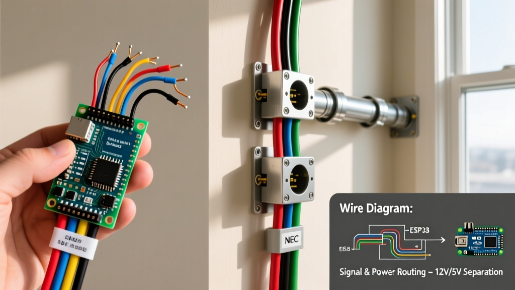
While 12V DC systems in homes often fall under NEC Article 720 (Circuits Less Than 50 Volts) or Article 690 (Solar Photovoltaic Systems), local Authority Having Jurisdiction (AHJ) interpretations vary wildly. Some inspectors require all low-voltage DC wiring to be routed in conduit if it shares a wall cavity with 120V AC mains. Always maintain a minimum 2-inch physical separation between your 12V DC parallel branch wiring and 120V AC branch circuits to prevent inductive coupling and accidental contact during future renovations.
For deeper reading on marine and off-grid DC circuit protection standards, refer to the Blue Sea Systems Circuit Protection guidelines, which closely mirror ABYC E-11 standards. For foundational theory on how current divides across parallel nodes, All About Circuits provides an excellent mathematical breakdown of Kirchhoff's Current Law as it applies to these exact node configurations.