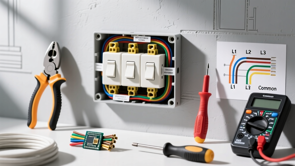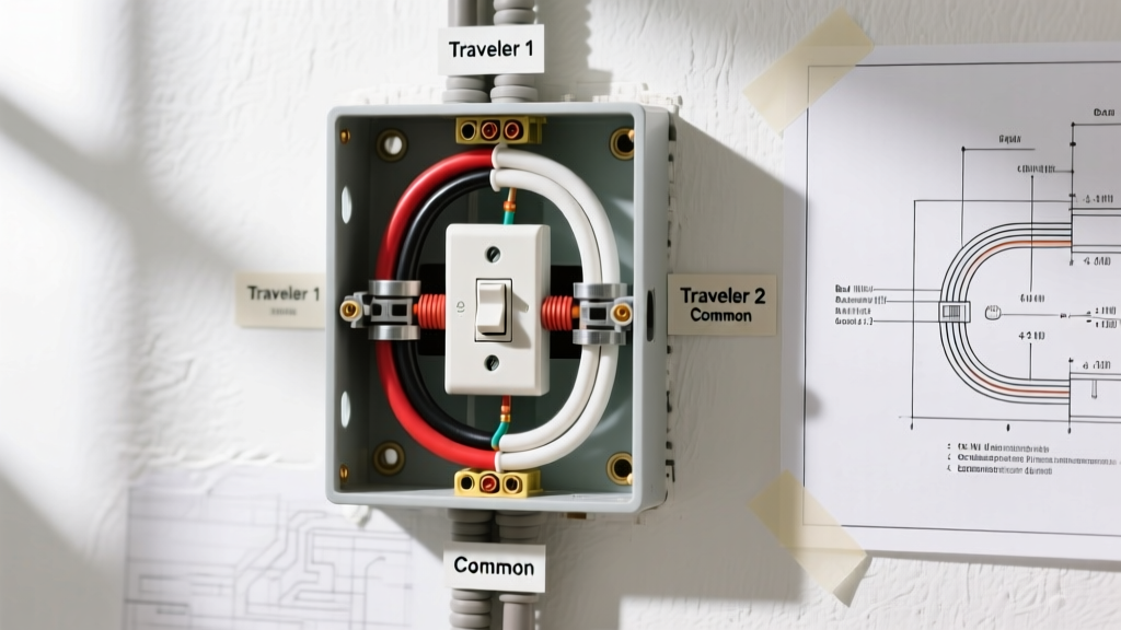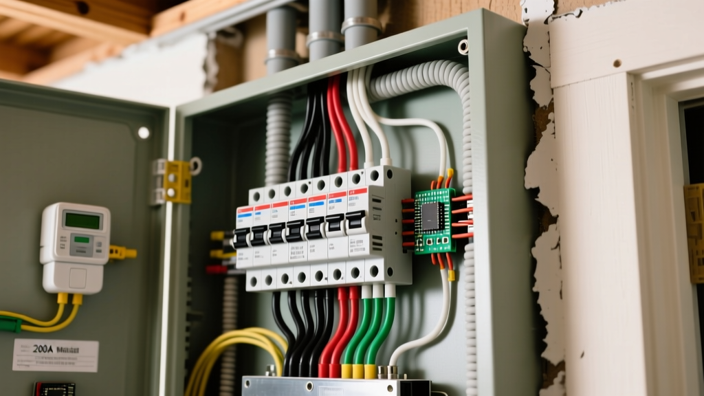

Upgrading or replacing a main service panel is one of the highest-stakes jobs in residential electrical work. When you are figuring out how to install a breaker panel for a modern 200-amp service, the margin for error is zero. A loose lug can cause an arc flash, and a missing bonding jumper can leave your home's grounding system completely ineffective during a fault. This guide walks through the exact procedure for terminating a 200A main service panel—using the industry-standard Square D QO or Homeline 200A main breaker enclosure as our reference model.
We will cover the exact wire gauges, the specific terminal landing points for every conductor color, the required torque values, and the verification steps you must complete before the utility re-energizes the meter.
Tools, Materials, and Service Conductor Specs
Before you pull a single wire, you need the right materials and a calibrated torque tool. The NEC now strictly requires that terminations be torqued to the manufacturer's specifications. Guessing by 'feel' is a code violation and a fire hazard.
- Panel: Square D QO 200-Amp 40-Space Main Breaker (Model QO140M200C) or equivalent Siemens 200A (P4040B1200C).
- Service Conductors: 4/0 AWG Aluminum XHHW-2 (in conduit) or 4/0-4/0-2/0 AL SER Cable.
- Grounding Electrode Conductor (GEC): #4 AWG Bare Copper (minimum for 200A service per NEC 250.66).
- Torque Screwdriver: Calibrated dial or digital torque screwdriver (e.g., Klein Tools 60345) capable of 250+ inch-pounds.
- Wire Prep: Oxide inhibitor paste (Noalox) for aluminum conductors, nylon wire brushes, cable strippers.
- Testing: CAT III / CAT IV True-RMS Digital Multimeter (e.g., Fluke 117) and a non-contact voltage detector.
200A Service Conductor & Torque Specification Table
The following table dictates the physical parameters for your service entrance conductors. Always defer to the specific label printed inside your panel's dead-front cover, as manufacturer specs can vary slightly by production year.
| Conductor Material | AWG Size | Insulation Type | Ampacity (75°C Col) | Main Lug Torque Spec |
|---|---|---|---|---|
| Aluminum (Standard) | 4/0 AWG | XHHW-2 / THWN-2 | 180A (Rated 200A per 310.12) | 250 in-lbs (Typical) |
| Copper (Premium) | 2/0 AWG | THHN / THWN-2 | 195A (Rated 200A per 310.12) | 300 in-lbs (Typical) |
| Aluminum SER Cable | 4/0-4/0-2/0 | XHHW-2 | 200A Service Rating | 250 in-lbs (Typical) |
| GEC (Grounding) | #4 AWG Copper | Bare | N/A (Fault path only) | 40 in-lbs (Bus bar screw) |
Source: NFPA 70 National Electrical Code (NEC) Articles 310.12 and 250.66.
Critical Safety Protocol: De-Energizing the Service
Working inside a main service panel involves exposed, unmetered utility voltage. You cannot simply 'turn off the main breaker' to make the service lugs safe—the utility feed coming into the top of the main breaker remains live at 240V with virtually unlimited fault current.
Required Protocol:
- Contact your local utility company to physically pull the meter or disconnect the service at the transformer/pole.
- Lock and tag out the meter base or utility disconnect.
- Once the utility confirms de-energization, use a CAT III/IV non-contact voltage tester on the service entrance conduit, followed by a True-RMS multimeter to verify 0.0V between the incoming service conductors and the ground bus.
- Never assume a pulled meter means the load-side jaws are dead; always test before touching. Local codes and OSHA regulations strictly mandate verified zero-energy states.
Step-by-Step Panel Termination
With the enclosure mounted to the studs and the service conduit or SER cable clamped into the top knockout, you are ready to terminate. The sequence matters: always land the ground first, then the neutral, and finally the hot conductors.
- Prep the Aluminum Conductors: Strip exactly 3/4-inch of insulation from the 4/0 AWG Black, Red, and White conductors. Use a nylon wire brush to scrub the exposed aluminum wire, then immediately coat it with Noalox oxide inhibitor paste. Aluminum oxidizes within minutes in air, creating a high-resistance layer that causes terminal heating.
- Land the Equipment Ground (Bare/Green): Take your #4 AWG Bare Copper Grounding Electrode Conductor (GEC) and route it to the dedicated ground bus bar. Terminate it under a single lug screw. Torque to the bus bar specification (usually 40 in-lbs). Note: In a main panel, the ground bar is physically bonded to the steel enclosure via a factory-installed strap or screw.
- Land the Service Neutral (White): Route the 4/0 AWG White (or gray) insulated neutral conductor to the main neutral bus bar. This is the larger bus bar with the heavier lugs, typically located on the right side of a Square D panel. Terminate the white wire under one of the large set-screws. Torque to 250 in-lbs. Do not place the neutral and the ground on the same terminal screw; one wire per lug.
- Install the Main Bonding Jumper (MBJ): This is the most critical step for a main service panel. Locate the green bonding screw (provided in the panel's hardware bag). Drive this screw through the neutral bus bar and directly into the steel back-can of the enclosure. This bonds the neutral to the ground, establishing the low-impedance fault return path required for the main breaker to trip during a ground fault. If this is a subpanel, skip this step and isolate the bars.
- Land the Hot Conductors (Black and Red): Route the 4/0 AWG Black and Red (or Black with red phase tape) conductors into the top lugs of the 200A Main Breaker. Ensure no bare wire is exposed outside the lug barrel, and no insulation is pushed inside the barrel. Tighten the set-screws using your calibrated torque screwdriver to exactly 250 in-lbs. You will hear a distinct 'click' when the dial torque tool reaches the threshold.
- Dress the Wires and Install Dead-Front: Neatly route the branch circuit wires, ensuring no conductors drape over the breaker toggles or pinch against the sharp edges of the knockout holes. Install the steel dead-front cover, securing all perimeter screws.
Verification and Load Testing
Once the utility replaces the meter and re-energizes the service, do not just flip the main breaker and walk away. You must verify the electrical physics of the installation before applying branch loads.
Set your True-RMS multimeter to AC Voltage (V~) and perform the following measurements at the main breaker terminals and the branch bus bars:
- Line 1 to Line 2 (Black to Red): Must read between 238V and 242V. If you read significantly lower (e.g., 208V), you may be on a commercial wye transformer, or there is a severe utility voltage drop.
- Line 1 to Neutral (Black to White): Must read 119V to 121V.
- Line 2 to Neutral (Red to White): Must read 119V to 121V.
- Neutral to Ground (White to Bare): Must read 0.0V to 0.5V. Any reading above 2V under no-load conditions indicates a poor neutral connection at the utility transformer or a missing main bonding jumper inside your panel.
Next, turn on heavy continuous loads (electric oven, HVAC compressor, EV charger) and re-measure Line-to-Neutral. According to Fluke's power quality testing guidelines, a voltage drop of more than 5% (below 114V) under full load indicates undersized service conductors or a failing utility transformer tap.
The Most Common Botch: The Floating Neutral
Symptom: Lights flicker wildly when the microwave turns on. Outlets on one side of the house read 90V, while outlets on the other side read 150V. Electronics are frying.
The single most dangerous and common mistake when learning how to install a breaker panel is failing to properly secure the neutral lug or forgetting the Main Bonding Jumper.
The Physics of the Botch: In a 120/240V split-phase system, the neutral carries the unbalanced current between the two hot legs. If the 4/0 neutral lug is loose, or if you forgot to install the green bonding screw, the neutral 'floats.' The two 120V legs effectively become a series circuit. If Leg 1 has a 1500W hair dryer and Leg 2 has a 15W LED bulb, the resistance imbalance forces the voltage to skew. The LED bulb might receive 220V (popping instantly), while the hair dryer receives only 30V (stalling the motor and causing a fire).
The Fix: Always torque the neutral lug to the exact manufacturer specification (250 in-lbs). Never reuse an aluminum lug that has been previously torqued and backed out, as the set-screw deforms the soft metal. If you are replacing an old panel and the existing neutral wire is too short to reach the new bus bar, do not use a wire nut to extend it inside the panel. Install an insulated terminal block or replace the service entrance cable entirely. Local AHJ inspectors will immediately fail a panel with a spliced service neutral or a missing bonding strap.