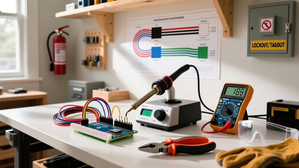

The Stakes of Residential Electrical Work
Electrical wiring is unforgiving. A single loose neutral, an overloaded junction box, or a failure to verify a de-energized circuit can result in catastrophic arc flashes, severe burns, or fatal electrocution. According to the National Fire Protection Association (NFPA), electrical failures or malfunctions are consistently a leading cause of home structure fires, causing billions in direct property damage annually. Furthermore, the U.S. Consumer Product Safety Commission (CPSC) emphasizes that improper DIY wiring and aging infrastructure are primary culprits in residential electrocution incidents.
Whether you are upgrading a 200-amp service panel, adding a dedicated 240V circuit for an EV charger, or simply swapping out a 15-amp duplex receptacle, safety is not a checklist—it is a continuous methodology. This guide details the rigorous, professional-grade safety best practices for electrical wiring that separate seasoned tradespeople from hazardous amateurs.
Phase 1: True Lockout/Tagout (LOTO) for Residential Panels
The most common and dangerous mistake DIYers make is assuming that flipping a breaker to the 'OFF' position and placing a piece of masking tape over it constitutes a safe lockout. Tape is not a physical barrier. In a busy household, a well-meaning family member can easily remove the tape and reset a tripped breaker while you are still terminating wires at a junction box.
Implementing Physical Isolation
Residential Lockout/Tagout requires a physical device that prevents the breaker handle from being moved.
- Breaker Lockouts: Use a universal breaker lockout device, such as the Master Lock 410 ProSeries or the Brady Zing Universal Breaker Lockout. These clamp directly onto the breaker toggle and require a padlock to secure.
- Padlocks: Use a dedicated, keyed-differently safety padlock (typically red or orange). You must hold the only key in your pocket while working on the circuit.
- Tags: Attach a durable danger tag indicating who is working on the circuit, the date, and the expected completion time.
Expert Insight: If you are working on the main service panel or the service drop conductors where the main breaker does not isolate the incoming utility feed, you must coordinate with your local utility company to physically disconnect the meter or drop. Never work on live service entrance conductors.
Phase 2: Verifying Dead — The Live-Dead-Live Protocol
Non-contact voltage testers (NCVTs), often called 'tic tracers' or 'wiggy' testers, are excellent for initial troubleshooting but are entirely insufficient for verifying a dead circuit. NCVTs detect electromagnetic fields and are highly susceptible to phantom voltages, shielding from metallic armor (BX/MC cable), and false negatives from dead batteries.
The Mandatory 3-Step Test
Before your hands ever enter an electrical box, you must perform the Live-Dead-Live test using a Category III (CAT III) or Category IV (CAT IV) rated digital multimeter (DMM) or a dedicated two-pole voltage tester like the Fluke T6-1000 or Klein Tools ET900.
- LIVE: Test your meter on a known, verified live source (e.g., an adjacent, active receptacle or a dedicated proving unit) to confirm the meter and leads are functioning correctly.
- DEAD: Test the target circuit. Measure Phase-to-Neutral, Phase-to-Ground, and Neutral-to-Ground. The reading must be exactly 0.00V.
- LIVE: Return to the known live source and test again to ensure the meter did not blow its internal fuse or fail during the second step.
Phase 3: Box Fill Calculations and Thermal Management
Overcrowding an electrical box is a severe fire hazard. Excess wires trap heat, degrade insulation, and make proper termination physically impossible, leading to loose connections. The National Electrical Code (NEC) Article 314 dictates strict box fill volume requirements based on the gauge of the conductors.
NEC Table 314.16(B) Volume Allowances
When calculating box fill, every current-carrying conductor, equipment grounding conductor (counted as one regardless of how many enter the box), and internal clamp counts toward the total volume. Devices (receptacles/switches) count as two conductors based on the largest wire connected to them.
| Conductor Size (AWG) | Volume Allowance per Conductor | Max 12 AWG Wires in Standard Single-Gang Box (18 cu in) |
|---|---|---|
| 14 AWG | 2.0 cubic inches | 9 conductors (including device allowance) |
| 12 AWG | 2.25 cubic inches | 8 conductors (including device allowance) |
| 10 AWG | 2.50 cubic inches | 7 conductors (including device allowance) |
Actionable Advice: Always use deep junction boxes (minimum 2.5 inches deep, yielding 22.5+ cubic inches for single-gang) when running 12 AWG wire for 20-amp circuits, especially in kitchens and bathrooms where GFCI and AFCI devices take up significant physical space.
Phase 4: Torque Specifications — The Hidden Fire Hazard
A loose terminal screw creates high electrical resistance. Under load, this resistance generates intense heat, leading to thermal cycling, oxidation, arcing, and ultimately, a fire. To combat this, NEC Section 110.14(D) mandates that terminations be tightened to the torque values specified by the manufacturer.
Executing Proper Terminations
You cannot achieve accurate torque by 'feel'. Professional electricians use calibrated torque screwdrivers or inch-pound torque wrenches.
- Standard 15A/20A Receptacles (12 & 14 AWG): Typically require 12 to 14 inch-pounds of torque.
- 30A Dryer/Range Receptacles (10 & 8 AWG): Typically require 20 to 25 inch-pounds.
- Panel Lugs (4 AWG to 1/0 AWG): Require specific inch-pound values printed on the panel label, often necessitating a 1/4-inch drive torque wrench (e.g., CDI 1501MFRMHSS).
Furthermore, always use insulated tools rated for 1000V, such as the Klein Tools 32500 series or Wiha Insulated SlimLine drivers, to protect against accidental slips onto adjacent live bus bars or terminals.
Phase 5: Termination Edge Cases and Failure Modes
How you physically terminate the wire to the device is just as critical as the torque applied.
The Danger of 'Backstabbing'
Many modern receptacles feature push-in (backstab) terminals. While UL-listed and legal for 14 AWG solid copper wire, these rely on a small internal spring clip to maintain contact. Over 15 to 20 years, thermal expansion and contraction can cause spring fatigue, leading to high-resistance failures behind the drywall. Best Practice: Always use the side-wire screw terminals. Form a tight, clockwise 'shepherd's hook' loop around the screw terminal so that tightening the screw pulls the loop closed rather than pushing it out.
Dealing with Legacy Aluminum Wiring
If your home was built between 1965 and 1973, it may contain solid aluminum branch circuit wiring. Aluminum oxidizes rapidly when exposed to air, creating a highly resistive layer that causes fires at copper-aluminum junctions.
- Never use standard purple wire nuts to pigtail aluminum to copper. Independent testing has shown they frequently fail under thermal load.
- Always use AlumiConn lug-style connectors or the King Innovations COPALUM crimp system, which are the only methods widely endorsed by the CPSC and insurance underwriters for permanent remediation.
Summary: Building a Safety-First Culture
Safe electrical wiring is not about moving fast; it is about moving deliberately. By enforcing strict Lockout/Tagout procedures, relying on the Live-Dead-Live verification protocol, calculating box fill to prevent thermal trapping, and utilizing calibrated torque tools for every termination, you ensure your electrical infrastructure is safe, code-compliant, and built to last. For further reading on residential electrical safety standards and arc flash awareness, consult the Electrical Safety Foundation International (ESFI) resources before beginning your next project.