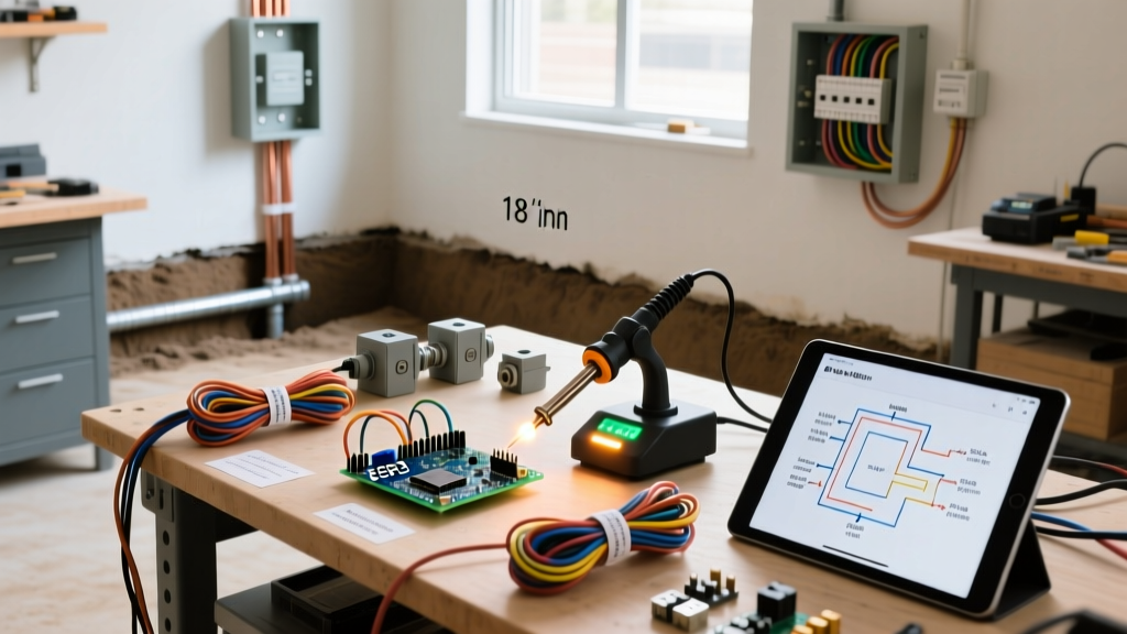
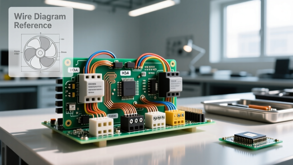
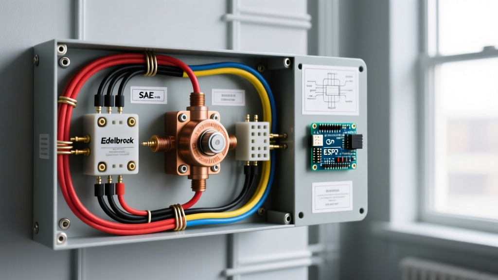
A 3 wire start stop circuit is a motor control configuration that uses three control wires to route power through a normally-closed STOP button, a normally-open START button, and a parallel holding contact to safely latch a contactor coil.
What it changes in a real installation: It transforms a motor from an automatic-restart hazard into a manually controlled machine. By requiring deliberate manual intervention to close the circuit, it ensures the motor stays dead after a power outage or voltage dip until an operator physically presses START again—a critical safety feature known as low-voltage protection.
What people commonly confuse it with: Beginners frequently confuse the "3 wires" with the three main power phases (L1, L2, L3) feeding a 3-phase motor. The "3-wire" designation actually refers to the logical control pilot wiring, not the main power feed. It is also commonly mixed up with 2-wire control, which uses a single maintained switch (like a thermostat) and lacks the safety latch-off behavior.
The Core Anatomy of a 3-Wire Control Circuit
To understand how this circuit operates, you have to look past the main power lugs and focus on the control circuit. The magic of the 3 wire start stop circuit lies in the sealing contact (also called a holding contact or latch contact). Think of the sealing contact like a deadbolt on a door: the START button pushes the door open, and the sealing contact slides the deadbolt into place so you can take your hand off the door handle.
When you press the momentary START pushbutton, 120VAC flows through the normally-closed STOP button, through the START button, and energizes the contactor coil. The coil pulls in the main power contacts to start the motor. Simultaneously, it pulls in an auxiliary normally-open (NO) contact wired in parallel with the START button. When you release the START button, power continues to flow to the coil through this newly closed auxiliary contact. To break the circuit, you press the STOP button, which interrupts the control power, drops the coil, and opens the auxiliary contact, resetting the system.
Standard Component Spec Sheet: 5 HP, 230V 3-Phase Starter
The following table outlines the exact components required for a standard NEMA Size 1, 3-wire motor control circuit operating on a 120VAC control voltage.
| Component | Specification / Rating | Function in 3-Wire Circuit | Example Part Number |
|---|---|---|---|
| Contactor | NEMA Size 1, 120VAC Coil (18VA sealed) | Switches main power; provides auxiliary NO holding contact | Allen-Bradley 100-C09EJ10 |
| Overload Relay | Class 10, Bi-metallic, 4.5A - 6.8A range | Provides NC contact in series with coil to drop circuit on thermal trip | Schneider Electric LRD10 |
| STOP Pushbutton | NEMA 1, Normally-Closed (NC), Red | Breaks control circuit continuity when pressed | Eaton M22-DPR |
| START Pushbutton | NEMA 1, Normally-Open (NO), Green | Momentarily completes control circuit to energize coil | Eaton M22-DPG |
| Control Fuse | Class CC, 2A Time-Delay, 600VAC | Protects 14 AWG control wiring from short circuits | Bussmann LPJ-2SP |
2-Wire vs. 3-Wire Control: The Safety Distinction
The most critical decision when designing a motor control panel is choosing between 2-wire and 3-wire control. While both will turn a motor on and off, their behavior during a power failure is drastically different. According to EC&M's motor control fundamentals, understanding this distinction is a baseline requirement for safe industrial wiring.
| Feature | 2-Wire Control | 3-Wire Control |
|---|---|---|
| Pilot Devices | Maintained switch (toggle, pressure, float) | Momentary pushbuttons (Start/Stop) |
| Wiring Complexity | 2 control wires to the switch | 3 control wires to the pushbutton station |
| Power Failure Behavior | Motor restarts automatically when power returns | Motor stays OFF until START is pressed again |
| Primary Use Case | Automated systems (HVAC compressors, sump pumps) | Operator-driven machinery (lathes, conveyors, saws) |
| Safety Profile | Hazardous for manual machinery (unexpected restart) | High safety (Low-Voltage Protection) |
If you wire a table saw with a 2-wire toggle switch and the shop loses power, the saw will violently restart the moment the utility restores the grid. If that same saw is wired with a 3 wire start stop circuit, the contactor drops out when the voltage sags, the sealing contact opens, and the operator must deliberately press the green START button to resume work.
Worked Numeric Example: Sizing the Control Circuit
Let’s size the control circuit for the 5 HP, 230V 3-phase motor starter outlined in our spec sheet above. We need to determine the control wire gauge and the control fuse sizing based on the contactor coil's electrical characteristics.
Given Values:
Control Voltage: 120VAC
Contactor Coil Sealed VA: 18 VA
Contactor Coil Inrush VA: 115 VA
Control Wire: 14 AWG THHN (Copper)
Step 1: Calculate Sealed and Inrush Current
The coil draws significantly more current for a fraction of a second when it first pulls in (inrush) compared to when it is fully seated (sealed).
Sealed Current (I_sealed) = VA / V = 18 / 120 = 0.15 Amps
Inrush Current (I_inrush) = VA / V = 115 / 120 = 0.95 Amps
Step 2: Select Control Wire Size
While 0.15A is minuscule, NEC Article 725 and standard industrial practices dictate that 14 AWG is the minimum practical size for control circuit wiring inside a motor control panel to ensure mechanical durability and terminal compatibility. 14 AWG THHN is rated for 15A at 60°C, which is vastly oversized for the 0.15A continuous load, but perfectly compliant and standard for the physical build.
Step 3: Size the Control Fuse
If we used a standard fast-acting 1A fuse, it would blow immediately every time someone pressed the START button because the 0.95A inrush current would spike the thermal element. Instead, we select a 2A Class CC Time-Delay fuse (like the Bussmann LPJ-2SP). The time-delay element ignores the 0.95A inrush spike lasting a few milliseconds, but will rapidly clear a dead short on the 14 AWG wire. As noted in Fluke's motor starter troubleshooting guides, nuisance tripping on control circuits is almost always caused by failing to account for coil inrush VA when selecting fuses.
Where You Meet This in Practice
You will encounter the 3 wire start stop circuit anywhere a human operator interacts directly with high-torque or high-inertia machinery. Here is where this specific topology dominates:
- Woodworking and Metalworking Machinery: Large cabinet saws, planers, and manual milling machines use 3-wire magnetic starters. The STOP button is often a large, red "palm paddle" that can be hit with a knee or elbow in an emergency, breaking the 3-wire control circuit and dropping the contactor.
- Shop Dust Collectors and Air Compressors: While small compressors use 2-wire pressure switches, large 5HP+ stationary compressors and cyclone dust collectors use 3-wire stations to prevent automatic cycling while a technician is changing filter bags or draining tanks.
- Industrial Conveyors and Packaging Lines: These systems use 3-wire control integrated with emergency stop (E-stop) relays. The E-stop circuit is wired in series with the standard STOP pushbutton, ensuring that any fault or manual stop breaks the sealing contact loop.
- Hydraulic Press Brakes: Safety standards require that ram movement only occurs upon deliberate, sustained operator input. The 3-wire circuit provides the foundational latching logic for the main hydraulic pump motor, ensuring it doesn't auto-restart mid-cycle after a voltage sag.
Safety Caveat: When troubleshooting or wiring a 3-wire control circuit, always remember that the control circuit may be energized from a separate source (like a control transformer) than the main motor power. De-energizing the main motor disconnect does not guarantee the 120VAC control circuit is dead. Always verify the control circuit is de-energized with a tested multimeter before touching pilot device terminals.
Frequently Asked Questions
Why is it called a "3-wire" circuit if I see 4 or 5 wires in the conduit?
The name refers to the three logical control connection points required at the pushbutton station (Line to Stop, Stop to Start, and the Holding Contact return). In physical reality, you might run a 4-conductor or 5-conductor cable to the station to include a ground wire, an indicator light wire, or a jog circuit wire, but the fundamental latching logic remains a "3-wire" topology.
Can I use a 3-wire start stop circuit for a single-phase 120V motor?
Yes, but you must use a contactor rated for the motor's full load amps (FLA) and ensure the control circuit is isolated. If your motor runs on 120V, you cannot safely use the same 120V lines for the control circuit without proper isolation or a step-down control transformer, as a stuck contactor could leave the motor energized even if the control fuse blows.