
When DIYers and professional electricians discuss conductors and electricity, the conversation almost exclusively revolves around wire sizing, ampacity charts, and NEC code compliance. However, the real battlefield of electrical troubleshooting lies in the hidden degradation of these conductors over time. A wire that is perfectly sized on day one can become a high-resistance failure point by year five due to environmental, thermal, and mechanical stresses. Understanding the physics of conductor degradation is the difference between endlessly replacing blown fuses and permanently solving the root cause of an electrical fault.
The Physics of Conductor Degradation
Electrical conductors do not exist in a vacuum. They are subjected to thermal cycling, mechanical vibration, and atmospheric contaminants. When troubleshooting persistent voltage drops or intermittent thermal trips, you must look beyond the breaker and examine the metallurgical reality of the wiring.
Thermal Creep and Cold Flow
One of the most insidious failure modes in modern wiring is thermal creep, particularly when dealing with aluminum conductors. Aluminum alloys (such as the AA-8000 series required by the National Fire Protection Association (NFPA 70)) have a Coefficient of Thermal Expansion (CTE) that is approximately 42% higher than that of copper. When an aluminum conductor is terminated under a copper or brass lug, the daily heating and cooling cycles cause the aluminum to expand and contract at a vastly different rate. Over time, this 'thermal ratcheting' causes the aluminum to cold flow away from the pressure point, resulting in a loose connection. A loose connection increases contact resistance, which generates localized heat (I²R losses), accelerating the creep until the terminal melts or arcs.
Galvanic Corrosion in Dissimilar Metals
Troubleshooting conductors and electricity often involves investigating historical repairs where dissimilar metals were improperly joined. Copper is cathodic, while aluminum is anodic. If these two metals are placed in direct physical contact in the presence of an electrolyte (even ambient humidity), a galvanic cell is formed. The aluminum will rapidly corrode, creating a layer of aluminum oxide. Because aluminum oxide is an electrical insulator, this corrosion layer acts as a resistor in series with the load, causing severe voltage drop and dangerous heat accumulation. The only code-compliant fixes for this are specialized pigtailing connectors like COPALUM (which requires a proprietary crimping tool) or AlumiConn lug connectors, which physically separate the metals and utilize anti-oxidant pastes.
Diagnostic Framework: Spotting Conductor Failures
Before tearing into walls or replacing expensive components, use this diagnostic matrix to correlate symptoms with specific conductor failure modes.
| Observed Symptom | Probable Root Cause | Diagnostic Tool / Method |
|---|---|---|
| Intermittent voltage drops under heavy load | Thermal ratcheting / loose terminal | Millivolt drop test under load; Thermal imaging camera |
| White, powdery residue at aluminum lugs | Galvanic corrosion / moisture ingress | Visual inspection; pH testing of residue |
| Overheating wires on VFD outputs | Skin effect / High-frequency PWM heating | Oscilloscope analysis; Conductor sizing review for carrier frequency |
| Breaker trips instantly; wire shows no continuity | Internal conductor fracture (hidden nick) | Time Domain Reflectometry (TDR) |
High-Frequency and Skin Effect Anomalies
A deeply misunderstood aspect of troubleshooting conductors and electricity involves alternating current (AC) behavior at non-standard frequencies. In standard 60Hz residential power, the 'skin effect'—where current is forced to the outer periphery of the conductor—is negligible for wires smaller than 4/0 AWG. The skin depth in copper at 60Hz is roughly 8.5mm.
However, in industrial or advanced DIY setups utilizing Variable Frequency Drives (VFDs) or high-frequency inverters, the Pulse Width Modulation (PWM) carrier frequencies can reach 10kHz to 20kHz. At 20kHz, the skin depth in copper shrinks to approximately 0.46mm. If a solid core wire or standard stranded wire is used, the center of the conductor carries virtually zero current, drastically increasing the effective AC resistance (Rac) compared to its DC resistance (Rdc). This leads to unexplained conductor overheating even when the wire is sized correctly for the RMS amperage. Troubleshooting this requires upsizing the wire, utilizing Litz wire (individually insulated strands woven to equalize flux linkage), or lowering the VFD carrier frequency to reduce the proximity and skin effects.
Step-by-Step Troubleshooting Protocol for Suspect Conductors
When you suspect a conductor is failing but visual inspection yields no answers, follow this rigorous testing protocol.
1. The Millivolt Drop Test
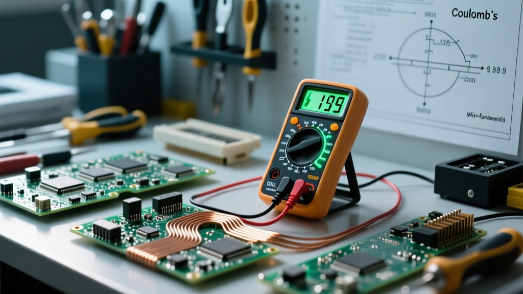
Standard voltage testing is often insufficient for finding high-resistance connections because the voltage drop might only manifest under peak load. Instead, perform a millivolt drop test. Using a high-precision multimeter (like the Fluke 87V), set the dial to DC or AC millivolts (depending on the circuit). Place the probes directly across the suspect connection (e.g., from the wire insulation edge to the busbar) while the circuit is under full operational load. According to Fluke Corporation's diagnostic guidelines, a healthy, tight connection should drop less than 3 millivolts. If you read 15mV or higher, the connection has degraded due to oxidation, thermal creep, or improper torque, and must be remade.
2. Time Domain Reflectometry (TDR)
If a conductor is failing intermittently or shows an open circuit but the ends look perfect, the break is hidden inside the insulation. This is common in underground UF-B cables or wires pulled through conduit with sharp bends. A Time Domain Reflectometer (such as the Megger TDR330) sends a high-frequency pulse down the wire. When the pulse hits an impedance mismatch (like a severe nick, a crushed section, or a water ingress point), it reflects back. The TDR calculates the exact distance to the fault based on the propagation velocity of the specific dielectric material, saving you from digging up an entire trench or pulling out 100 feet of wire blindly.
Prevention and Material Selection
The ultimate goal of troubleshooting is to implement a permanent fix. To prevent conductor degradation in new installations or repairs, strict adherence to material science and torque specifications is mandatory.
- Anti-Oxidant Compounds: When terminating aluminum or copper-aluminum transitions, always apply a UL-listed anti-oxidant paste (such as Ideal No. 35-926 Noalox). These pastes contain zinc dust suspended in a polybutene base. The zinc acts as a sacrificial anode, while the paste excludes moisture and oxygen, halting galvanic corrosion.
- Calibrated Torque: The NEC (Section 110.14(D)) now strictly requires the use of calibrated torque tools for terminations. Guessing 'tight enough' with a standard screwdriver leads to over-torquing (which strips threads and crushes soft aluminum) or under-torquing (which guarantees thermal creep). Use a calibrated torque screwdriver, like the Klein Tools 70005, set exactly to the manufacturer's inch-pound specification printed on the breaker or lug.
- Strand Management: Never tin stranded copper wire with solder before inserting it into a screw-terminal lug. Solder exhibits severe cold flow under pressure. Over a few months, the solder will deform, the connection will loosen, and a fire hazard is created. Use ferrules or stick to bare stranded/solid copper as specified by the Copper Development Association (CDA).
Expert Insight: Troubleshooting conductors and electricity is rarely about the wire itself failing in the middle of a run; it is almost always about the termination points. 95% of all conductor-related electrical fires and failures occur within the first two inches of a lug, breaker, or wire nut. Focus your diagnostic efforts on the connections, not the cable jacket.
By shifting your perspective from simple continuity testing to an understanding of metallurgical stress, thermal dynamics, and high-frequency skin effects, you elevate your troubleshooting from basic guesswork to true electrical diagnostics. Whether you are maintaining a home subpanel or debugging a complex VFD motor circuit, respecting the physical limitations of your conductors is the key to a safe, reliable electrical system.