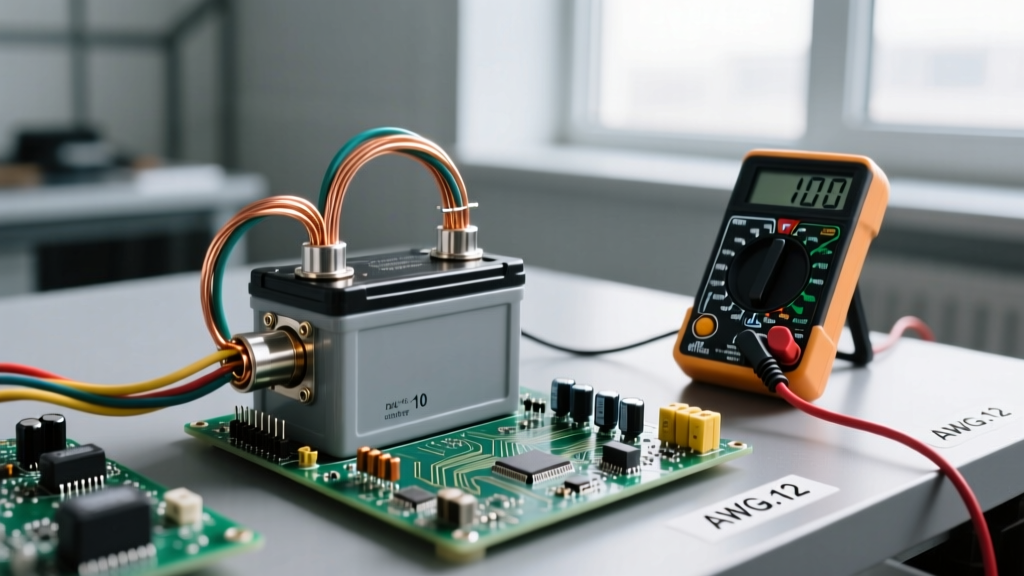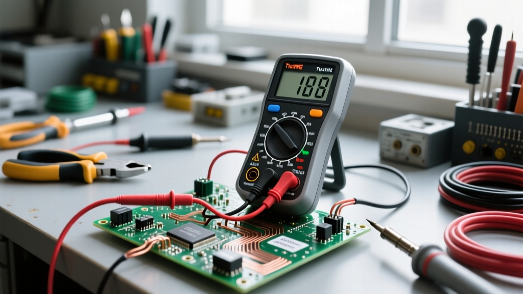

Troubleshooting an alternating current circuit requires a fundamentally different mindset than diagnosing DC electronics or simple resistive loads. In DC systems, electrons flow uniformly in a single direction, making voltage drop and continuity relatively straightforward to trace. In AC systems, however, the continuous reversal of current direction—typically 60 times per second (60Hz) in North America—introduces complex variables like reactance, impedance, inductive coupling, and harmonic distortion. When an AC branch circuit or feeder fails, misinterpreting these variables can lead to misdiagnosed faults, unnecessary wire replacements, or severe arc flash hazards.
The Hidden Dangers of AC Diagnostics and Tool Selection
Before probing any live alternating current circuit, verifying your test equipment's safety rating is non-negotiable. A standard electronics multimeter rated for CAT I or CAT II is entirely inadequate for panel-level or branch-circuit AC troubleshooting. A transient voltage spike on a 120V/240V AC branch circuit can easily exceed 6,000V. If your meter lacks the internal arc-blast shielding and high-energy fuses required for a CAT III 600V or CAT IV 600V environment, that transient can vaporize the meter's internal shunts, causing a catastrophic failure in your hands.
For professional AC diagnostics, tools like the Fluke 117 Electricians True RMS Multimeter or the Fluke 87V Industrial Multimeter are industry standards. These meters are specifically engineered to handle the harsh electromagnetic environments found in commercial and residential AC distribution systems, providing accurate readings even in the presence of severe electrical noise.
Why Your Standard Multimeter Might Be Lying to You
One of the most common mistakes DIYers and junior technicians make when troubleshooting an alternating current circuit is using an average-responding multimeter on modern, non-linear loads. Older AC circuits primarily served resistive or linear inductive loads (incandescent lighting, resistive heaters, standard induction motors), which draw a clean, sinusoidal current wave.
Today's circuits are dominated by non-linear loads: LED drivers, variable frequency drives (VFDs), and switch-mode power supplies (SMPS) found in computers and servers. These devices draw current in abrupt, high-amplitude pulses rather than a smooth sine wave. An average-responding meter calculates the RMS (Root Mean Square) voltage by measuring the rectified average and multiplying it by a fixed form factor (1.111). When faced with a distorted waveform, this mathematical assumption collapses, often resulting in readings that are 10% to 40% lower than the actual effective voltage. To accurately troubleshoot modern AC circuits, a True RMS multimeter is mandatory, as it samples the waveform directly to calculate the true heating effect of the distorted AC signal.
The 3 Most Common Alternating Current Circuit Faults
Fault 1: Phantom Voltage and Capacitive Coupling
You are troubleshooting a dead 120V receptacle on a 12/3 NM-B (Romex) cable run. You disconnect the hot wire at the panel and measure the voltage to ground, expecting 0V. Instead, your high-impedance digital multimeter reads 45V. Is the circuit back-fed? Is there a dangerous cross-connection?
Likely, no. This is phantom voltage caused by capacitive coupling. In a multi-conductor AC cable, the parallel wires act as the plates of a capacitor, separated by the PVC insulation. The energized black wire induces an AC voltage onto the disconnected, floating red wire. Because modern digital multimeters have an input impedance of roughly 10 Megohms, they require almost zero current to register a voltage reading. To prove this is phantom voltage, switch your meter to LoZ (Low Impedance) mode, or use a solenoid tester (a 'Wiggy'). The LoZ mode introduces a deliberate low-resistance path that bleeds off the capacitively coupled ghost voltage, dropping the reading to a true 0V.
Fault 2: Neutral-to-Earth Voltage (N-E) Drop
In a properly functioning single-phase alternating current circuit, the voltage between Neutral and Ground (Earth) should be near zero. However, when troubleshooting voltage-sensitive equipment that keeps resetting, you might measure 118V from Line-to-Neutral (L-N), but only 114V from Line-to-Ground (L-G). This indicates a 4V Neutral-to-Earth potential difference.
According to Ohm's Law, the neutral wire has inherent resistance. As load current flows back to the panel on the neutral conductor, a voltage drop occurs. If the N-E voltage exceeds 2.0V to 3.0V at the receptacle, it indicates an overloaded neutral, an excessively long wire run without adequate gauge upsizing, or a loose, oxidized neutral termination at the panel lug. In commercial settings, this is often exacerbated by shared neutrals on Multi-Wire Branch Circuits (MWBC) where out-of-balance harmonic currents stack up on the neutral bar.
Fault 3: Harmonic Distortion and Overheating Neutrals
If you are troubleshooting a commercial AC circuit feeding a data center or an LED lighting array, you may find the neutral conductor running dangerously hot, even when an AC clamp meter shows the neutral current is lower than the phase current. This is a classic symptom of triplen harmonics (3rd, 9th, 15th harmonics). Unlike fundamental 60Hz currents, which cancel out on the neutral in a balanced multi-phase system, triplen harmonics are zero-sequence and add arithmetically on the neutral. This can cause the neutral current to exceed the phase current by up to 1.73 times, leading to insulation degradation and potential fires. Troubleshooting this requires a Power Quality Analyzer capable of measuring Total Harmonic Distortion (THD).
Diagnostic Matrix: AC Circuit Symptom vs. Root Cause
Use this field-tested matrix to rapidly isolate faults in single-phase and three-phase alternating current circuits:
| Observed Symptom | Measured Value / Behavior | Probable Root Cause | Corrective Diagnostic Action |
|---|---|---|---|
| Breaker trips instantly upon energization | 0 Ohms (L-G or L-N); Infinite inrush | Dead short circuit or ground fault | Isolate circuit segments; perform de-energized Megohmmeter test. |
| Flickering LEDs or motor humming | Voltage swings wildly (e.g., 105V to 128V) | Loose utility neutral or corroded panel bus | Check utility transformer drop; torque panel neutral lugs to spec. |
| Shock from appliance chassis | N-G Voltage > 3.0V; Current on EGC | Broken Equipment Grounding Conductor (EGC) or N-E bond fault | Verify EGC continuity back to panel; check for illegal N-G bonds downstream. |
| Receptacle reads 'Hot' but won't power a load | 120V no-load; drops to <10V under load | High-resistance series fault (broken strand or backstab failure) | Apply a dummy load (e.g., incandescent lamp) and re-test voltage. |
Step-by-Step Insulation and Continuity Testing (De-energized)
When a fault in an alternating current circuit cannot be found using live voltage measurements, you must transition to de-energized insulation testing. Standard multimeters use a 3V to 9V DC battery to test continuity, which is entirely insufficient for detecting microscopic insulation breakdowns in 120V/240V or 480V AC wiring.
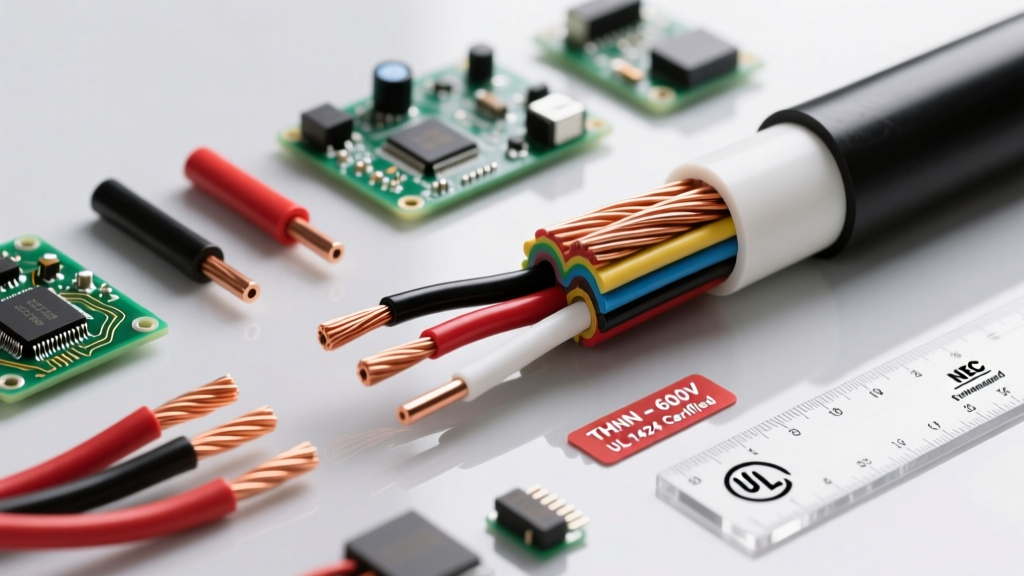
For AC circuits wired with 600V-rated insulation (such as THHN or XHHW-2), you must use a Megohmmeter (Megger) set to 500V or 1000V DC. This high-potential test stresses the wire insulation, revealing moisture ingress, nail punctures, or thermal degradation that a standard meter will miss.
- Lockout/Tagout (LOTO): Verify the circuit is fully de-energized using a live-dead-live test protocol.
- Isolate Sensitive Electronics: Disconnect all VFDs, smart switches, and surge protectors. The 1000V DC test potential will instantly destroy solid-state AC components.
- Test Phase-to-Ground: Connect the Megger's positive lead to the AC hot conductor and the negative lead to the bare copper EGC. Apply 1000V DC for 60 seconds.
- Interpret the Results: According to NETA (InterNational Electrical Testing Association) standards, newly installed AC wiring should read in the hundreds of Megohms. A reading below 1 Megohm indicates compromised insulation that requires immediate wire replacement or splice repair.
Pro-Tip from the Field: When troubleshooting voltage drop on long underground AC feeder runs, always measure the voltage at the source (panel lugs) and the load simultaneously using two synchronized True RMS meters. If the source voltage sags when the load kicks on, the issue is an undersized utility transformer or utility service drop, not your branch circuit wiring. For more on power quality diagnostics, refer to the guidelines published by EC&M (Electrical Construction & Maintenance).
Summary
Troubleshooting an alternating current circuit is an exercise in applied physics and rigorous safety protocols. By upgrading to True RMS diagnostic tools, understanding the deceptive nature of phantom voltages, and utilizing high-potential insulation testing, you can accurately isolate AC faults that standard trial-and-error methods will inevitably miss. Always prioritize NEC-compliant grounding and bonding practices to ensure your diagnostic baseline remains accurate and safe.