
The Hidden Hazard: How Electric Charges Accumulate in the Workshop
Every electrical project, from soldering a simple microcontroller to wiring a 240V subpanel, involves the manipulation of electric charges. While most DIYers focus on voltage and current, the fundamental accumulation and sudden release of static and dynamic electric charges present two distinct, often misunderstood safety hazards. Understanding the physics of these charges is not merely academic; it is the difference between a successful build and a catastrophic failure—either to your expensive silicon components or your own cardiovascular system.
The Physics of Charge Movement: Conductors vs. Insulators
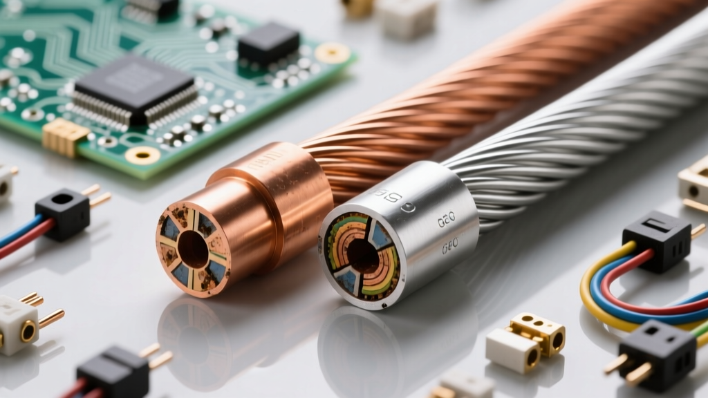
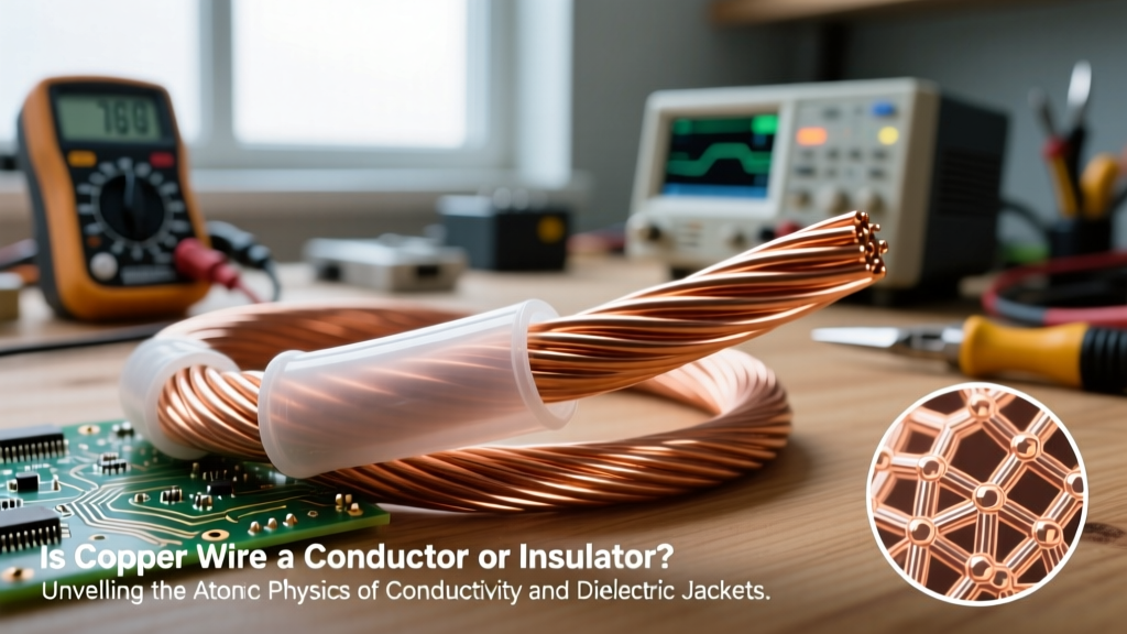
At the most fundamental level, all electrical safety revolves around controlling the movement of electric charges. Materials are classified by their atomic structure: conductors (like copper and aluminum) have loosely bound valence electrons that readily flow when subjected to an electromotive force (voltage). Insulators (like PVC, Teflon, and rubber) have tightly bound electrons that resist this flow. However, no insulator is perfect. When the accumulation of electric charges creates a voltage differential that exceeds the dielectric strength of the insulator, the material undergoes dielectric breakdown. For standard air, this breakdown occurs at roughly 3,000 volts per millimeter. This is why a static spark can literally jump across an air gap from your finger to a grounded chassis, bypassing physical barriers and damaging internal circuitry.
The Triboelectric Effect in the Modern Maker Space
In a typical home workshop, electric charges accumulate primarily through the triboelectric effect. This is the transfer of electrons when two dissimilar materials come into contact and separate. The modern maker space is a minefield of triboelectric hazards. Consider the operation of a desktop 3D printer: the continuous friction of PLA or ABS filament being dragged through PTFE (Teflon) tubing generates significant static charge. Similarly, rapidly peeling Kapton tape or masking tape off a workbench can generate localized electrostatic fields exceeding 10,000 volts. In low-humidity environments (below 30% relative humidity, common in winter or heavily air-conditioned spaces), the air lacks the moisture required to naturally dissipate these charges. Consequently, a DIYer can easily become a walking capacitor, harboring enough potential to instantly destroy sensitive silicon.
Static vs. Dynamic: Divergent Safety Protocols
When formulating a safety guide for electrical fundamentals, we must bifurcate our approach based on the nature of the electric charges involved. Static charges (stationary electrons) are a primary threat to microelectronics, causing Electrostatic Discharge (ESD). Dynamic charges (moving electrons, or current) and stored dynamic charges (in capacitors) are the primary threats to human life.
According to the ESD Association, the human body cannot perceive a static discharge below 3,000 volts. Yet, modern surface-mount MOSFETs can be permanently destroyed by a discharge of just 20 volts. You will never feel the spark that kills a $50 microcontroller.
Defeating Electrostatic Discharge (ESD) in Microelectronics
Protecting sensitive components from stray electric charges requires establishing an equipotential workspace. This means ensuring that you, your tools, and the components all share the exact same electrical potential, eliminating the voltage differential required for a discharge.
| Component Type | ESD Sensitivity Threshold | Common Workshop Hazard |
|---|---|---|
| MOSFET / CMOS ICs | 10V - 100V | Peeling Kapton tape, handling without wrist strap |
| EPROM / EEPROM | 100V - 500V | Sliding plastic IC tubes across a workbench |
| Discrete Transistors | 300V - 700V | Friction from synthetic clothing |
| Human Perception | ~3,000V | Touching a grounded doorknob |
Implementing the Human Body Model (HBM) Defense
To safely bleed off static electric charges from your body, a 1-megohm (1MΩ) resistor must be integrated into your ESD wrist strap. This specific resistance value is a critical safety compromise: it is low enough to dissipate thousands of volts of static charge in milliseconds, but high enough to limit current to a safe, non-lethal microamp level if you accidentally touch a live 120V or 240V AC circuit while grounded. Never use a simple copper wire to ground yourself to a workbench.
Lethal Accumulation: The Capacitor Discharge Threat
While static electricity threatens silicon, stored dynamic electric charges in capacitors threaten human life. Capacitors in switching power supplies, microwave ovens, and motor start circuits hoard massive amounts of electrical energy. The energy stored in a capacitor is calculated using the formula E = ½CV², as detailed by HyperPhysics at Georgia State University.
Consider the primary filter capacitor in a standard ATX computer power supply or a DIY LED driver: a 220µF capacitor rated at 400V DC. If fully charged, it stores approximately 17.6 Joules of energy. Medical literature suggests that an energy discharge as low as 10 to 50 Joules across the human chest can induce ventricular fibrillation. If you bridge the terminals of this capacitor with your fingers or a poorly insulated tool, the resulting shock can be fatal.
Calculating and Installing the Bleeder Resistor
To mitigate the hazard of stored electric charges, high-voltage capacitors must be equipped with a bleeder resistor. This resistor safely dissipates the stored charge when the power is removed. Let us calculate the required resistance to discharge our 220µF, 400V capacitor to a safe level (less than 1% of initial voltage) within 10 seconds.
Using the capacitor discharge time constant formula where t = 4.6 × R × C for a 99% discharge:
- 10 seconds = 4.6 × R × 0.000220 Farads
- R = 10 / (4.6 × 0.000220)
- R ≈ 9,864 Ohms
A standard 10kΩ, 5-watt wirewound resistor placed in parallel with the capacitor will safely neutralize the lethal electric charges in roughly 10 seconds after unplugging the device. Always verify with a multimeter before touching the circuit.
Wire Sizing and the Thermal Limits of Moving Charges
While static electric charges threaten microelectronics, the continuous flow of dynamic electric charges (current) introduces thermal hazards that dictate wire sizing fundamentals. Ampacity—the maximum continuous electric current a conductor can carry without exceeding its temperature rating—is essentially a measure of how many moving electric charges a wire can safely handle. When electrons flow through a copper conductor, they collide with the atomic lattice, generating heat (I²R losses). If the wire gauge is undersized for the load, the accumulation of thermal energy will melt the insulation, leading to short circuits, arc faults, and structural fires. This is why the National Electrical Code (NEC) mandates strict wire sizing charts based on conductor material, ambient temperature, and insulation type (e.g., THHN vs. XHHW). Managing electric charges safely means ensuring the physical pathway is robust enough to handle the volume of flow without thermal degradation.
Equipotential Bonding: The Ultimate Charge Equalizer
In larger wiring projects, managing electric charges extends to the physical infrastructure of your home or workshop. The Occupational Safety and Health Administration (OSHA) and the National Electrical Code (NEC) mandate strict grounding and bonding protocols to manage fault currents and static accumulation in hazardous environments.
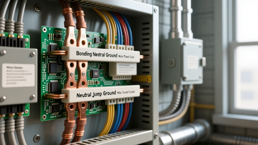
It is vital to understand the difference between an Equipment Grounding Conductor (EGC) and an Equipment Bonding Jumper. The EGC provides a low-impedance path back to the source to trip a breaker during a dynamic fault (a short circuit). Bonding, however, connects all non-current-carrying metal parts together to ensure they remain at the same electrical potential. If a static charge or an induced voltage accumulates on a metal chassis, bonding ensures that no potential difference exists between the chassis and the floor you stand on, completely eliminating the risk of a shock.
Real-World Grounding Mistakes in DIY Workshops
A common, highly dangerous mistake among DIYers is relying on a grounding rod driven into the earth as the sole method for clearing fault charges. Earth ground is excellent for dissipating slow-moving static electric charges (like lightning or triboelectric buildup), but it is entirely inadequate for clearing dynamic AC fault currents. The impedance of the soil is too high to draw the hundreds of amps required to trip a 20A breaker in milliseconds. Always ensure your workshop circuits utilize a continuous, properly sized copper EGC routed back to the main service panel's neutral-to-ground bond.
By respecting the physics of electric charges—whether they are static electrons threatening your microcontrollers or stored Joules threatening your heart—you transform your workshop from a zone of hidden hazards into a controlled, professional environment.