
Beyond the Textbook: What the Flow of Electric Charge Actually Means
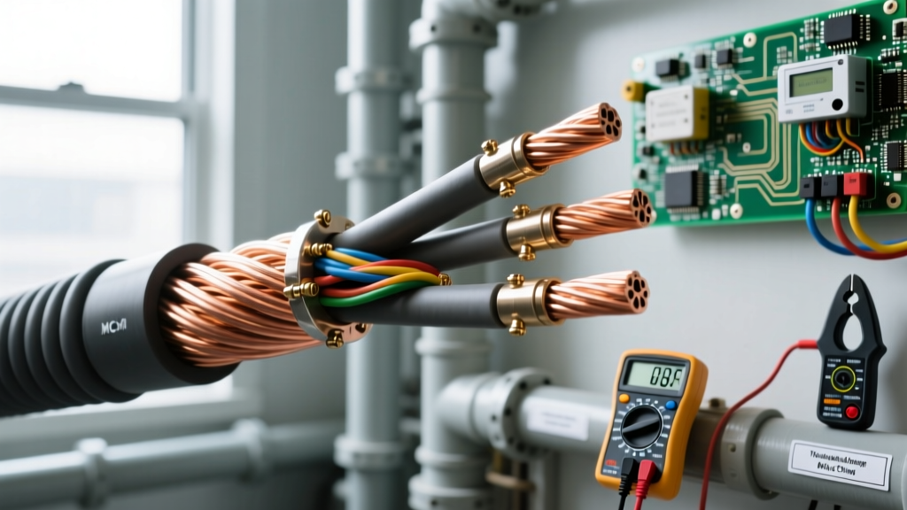
When most DIYers and beginner electricians think about the flow of electric charge, they picture a simple, water-like stream of electrons rushing through a copper pipe. While this hydraulic analogy is useful for understanding basic Ohm's Law, it completely falls apart when you are sizing conductors for a 200-amp residential service, troubleshooting voltage drop on a long feeder run, or dealing with high-frequency harmonic distortion in a modern workshop. To truly master wire sizing and electrical fundamentals, we must look at charge flow through the lens of real-world physics and practical application.
Electric current is defined as the rate at which charge passes through a given cross-sectional area of a conductor. But how those charge carriers (electrons) interact with the atomic lattice of the copper or aluminum wire dictates everything from insulation temperature limits to circuit breaker tripping curves. According to the foundational texts at All About Circuits, understanding the microscopic behavior of charge flow is what separates a theoretical hobbyist from a master electrician who can predict system failures before they happen.
Drift Velocity vs. Signal Propagation: Why Lights Turn On Instantly
A common point of confusion in electrical theory is the speed of the flow of electric charge. If you flip a switch at the end of a 100-foot hallway, the light turns on instantly. Therefore, electrons must be moving near the speed of light, right? Wrong. The actual physical movement of individual electrons—known as drift velocity—is astonishingly slow, often less than a single millimeter per second in standard residential wiring.
What actually travels near the speed of light is the electromagnetic wave (the signal) that propagates through the dielectric field surrounding the wire, pushing the free electrons already present in the conductor. Why does this matter for real-world wiring? Because when you are running long, parallel data and power cables, it is the electromagnetic field interaction (inductive and capacitive coupling) that causes crosstalk and signal degradation, not the physical collision of electrons. Understanding this distinction is critical when separating low-voltage communication lines from 120V/240V power lines to maintain signal integrity.
Joule Heating: When Charge Flow Meets Atomic Resistance
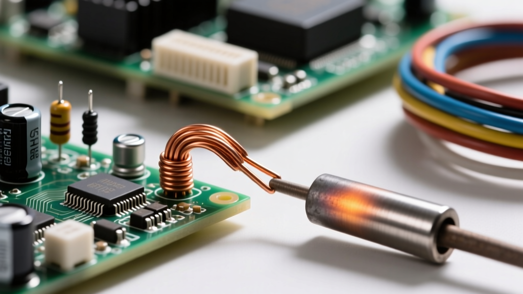
As the flow of electric charge is forced through a conductor, electrons constantly collide with the fixed atoms of the copper lattice. These collisions transfer kinetic energy into thermal energy, a phenomenon known as Joule heating (or I²R heating). This is the fundamental reason why wire gauge sizing exists. The National Electrical Code (NEC) ampacity tables are not arbitrary numbers; they are strictly based on the maximum amount of charge flow a conductor can handle before the resulting heat degrades the wire's insulation.
Real-World Ampacity Derating
If you pull four current-carrying conductors through a single conduit in a hot attic, the ambient heat and the mutual heating of the charge flow require you to derate the wire's ampacity. For example, a 12 AWG THHN wire is rated for 30 amps at 90°C in free air. However, if you have four conductors in a raceway, you must apply an 80% adjustment factor. The physical flow of electric charge hasn't changed, but the conductor's ability to dissipate the resulting thermal energy has, meaning you must upsize to 10 AWG to maintain safety margins.
| AWG Size | Circular Mils | DC Resistance (Ω/1000ft) | 90°C THHN Max Ampacity | Real-World Continuous Limit (80%) |
|---|---|---|---|---|
| 14 | 4,110 | 3.14 | 25A | 15A (NEC 240.4(D) restricts to 15A) |
| 12 | 6,530 | 1.98 | 30A | 20A |
| 10 | 10,380 | 1.24 | 40A | 30A |
| 8 | 16,510 | 0.778 | 55A | 40A |
| 6 | 26,240 | 0.491 | 75A | 55A |
The Skin Effect: AC Charge Flow Dynamics
When dealing with Direct Current (DC), the flow of electric charge is distributed evenly across the entire cross-sectional area of the wire. However, Alternating Current (AC) behaves entirely differently due to the skin effect. As alternating magnetic fields induce eddy currents within the conductor, they force the majority of the electron flow toward the outer surface (the 'skin') of the wire.
At the standard North American frequency of 60Hz, the skin effect is largely negligible for conductors smaller than 2/0 AWG. But in modern real-world applications—such as the high-frequency output of Variable Frequency Drives (VFDs), solar inverter outputs, or switch-mode power supplies—the frequency can reach into the kilohertz range. At these frequencies, the center of a solid thick conductor carries almost zero charge. This is why high-frequency applications require specialized Litz wire (many individually insulated thin strands) or large conductors must be hollow or segmented to eliminate the 'dead' copper in the center that adds weight and cost without carrying current. You can read more about the mathematical breakdown of this phenomenon on Electrical Technology's guide to the skin effect.
Triplen Harmonics: The Hidden Danger in Neutral Charge Flow
One of the most dangerous real-world manifestations of charge flow occurs in commercial or advanced DIY workshops utilizing non-linear loads like LED drivers, computers, and VFDs. These devices draw current in abrupt pulses rather than smooth sine waves, creating harmonic distortion.
While positive and negative sequence harmonics cancel out on the neutral conductor, triplen harmonics (3rd, 9th, 15th) are in-phase with each other. Instead of canceling, the flow of electric charge from these harmonics adds up arithmetically on the neutral wire. In a heavily loaded multi-wire branch circuit or a 3-phase wye system, the neutral conductor can actually experience more charge flow and generate more heat than the phase conductors. If an electrician sizes the neutral wire identically to the phase wires based on standard assumptions, the neutral will overheat, potentially melting the insulation and causing a fire. The modern solution is to oversize the neutral conductor by at least 200% in harmonic-heavy environments.
Troubleshooting Flow Bottlenecks: Connection Torque and Arcing
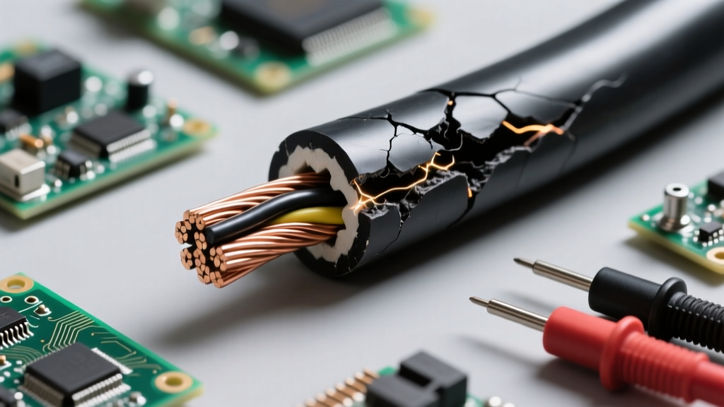
The flow of electric charge demands a continuous, low-resistance path. When it encounters a bottleneck—such as a loose terminal screw on a receptacle or a poorly crimped lug—the localized resistance spikes. According to Joule's Law, heat generation increases with the square of the current. A loose connection doesn't just cause a voltage drop; it creates a localized thermal hotspot.
As the metal heats and cools with the daily load cycle, it expands and contracts, loosening the connection further. Eventually, the flow of electric charge begins to jump the microscopic air gap, creating an electrical arc. This arc can reach temperatures exceeding 10,000°F, easily igniting surrounding wood framing or insulation. This exact failure mode is why the NEC now mandates the use of Arc Fault Circuit Interrupters (AFCIs) in most residential living spaces, and why professional electricians use calibrated torque screwdrivers (typically set between 14 and 20 in-lbs for standard 15A/20A devices) to ensure the physical connection can handle the electromagnetic forces of charge flow.
'Current is not merely the presence of electrons, but the directed, continuous drift of charge carriers driven by an electromotive force. Any restriction in this flow manifests immediately as thermal energy or electromagnetic radiation.' — HyperPhysics, Georgia State University
Summary: Designing for the Reality of Charge Flow
Mastering the flow of electric charge means looking past the simple 'Amps = Volts / Ohms' equation. It requires you to consider the thermal limits of insulation, the magnetic fields pushing electrons to the surface of AC conductors, the additive dangers of triplen harmonics on neutral buses, and the mechanical torque required to keep atomic lattices connected. By applying these real-world physics principles to your wire sizing and circuit design, you ensure systems that are not just code-compliant, but fundamentally robust and safe for decades of operation.