
If you have ever wired a 12V LED strip, connected a solar charge controller, or swapped a car battery, you have worked with direct current. But what is direct current exactly, and why does it behave so differently from the power coming out of your wall outlets? For DIY electronics enthusiasts, microcontroller hobbyists, and off-grid solar builders, understanding the fundamentals of DC power is not just academic—it is essential for designing safe, efficient, and functional circuits.
In this beginner's guide, we will break down the physics of direct current, explore its most common sources, and dive deep into the critical wiring fundamentals—like voltage drop and DC arcing—that every maker and electrician must know.
Understanding the Physics: How Electrons Move in DC
At its core, electricity is the movement of electrons through a conductive material, such as a copper wire. The term "current" refers to the rate of this flow. So, what is direct current from a physics perspective?
Direct current (DC) is the unidirectional flow of electric charge. In a DC circuit, electrons move steadily in a single direction from the negative terminal, through the conductive path, and back to the positive terminal.
Unlike alternating current (AC), which periodically reverses its direction of flow (typically 60 times per second in North America, known as 60Hz), DC maintains a constant polarity. The voltage in a pure DC circuit ideally remains flat and steady over time, creating a continuous, non-fluctuating push of electrons. This steady state is exactly why microcontrollers, logic gates, and sensitive semiconductor components require DC power to operate correctly; they rely on stable high and low voltage states to process binary data.
The Core Sources of DC Power
While the electrical grid delivers AC power to your home, most modern portable and renewable technologies generate or rely on DC. Here are the three primary ways DC power is produced:
1. Electrochemical Cells (Batteries)
Every battery—from a standard AA alkaline cell to a massive 12V Lithium Iron Phosphate (LiFePO4) marine bank—generates direct current through chemical reactions. Inside the battery, an electrochemical potential difference is created between the anode (negative) and cathode (positive). When a circuit is closed, electrons flow unidirectionally from the anode to the cathode. Because the chemical reaction only proceeds in one direction, the resulting current is inherently DC.
2. Photovoltaic Cells (Solar Panels)
Solar panels convert sunlight directly into electricity via the photovoltaic effect. When photons from the sun strike the silicon cells, they knock electrons loose, creating a flow of electric charge. Because the physical structure of the P-N junction in the solar cell only allows electrons to flow in one direction, the output is pure DC. According to the U.S. Department of Energy, this DC power must either be used directly in DC appliances or sent through an inverter to become AC for home use.
3. Rectifiers and Power Supplies
When you plug your laptop charger or a 5V USB power supply into the wall, you are using a rectifier. These devices take 120V AC from the grid and convert it into low-voltage DC. They use components like diodes (which act as one-way valves for electricity) and capacitors to smooth out the resulting waveform, providing the clean, steady DC voltage required by your electronics.
Direct Current vs. Alternating Current: A Side-by-Side Comparison
To truly understand what is direct current, it helps to contrast it directly with AC. Here is a technical breakdown of how they compare across vital electrical parameters:
| Parameter | Direct Current (DC) | Alternating Current (AC) |
|---|---|---|
| Electron Flow | Unidirectional (Constant) | Bidirectional (Oscillating) |
| Frequency | Zero (0 Hz) | 50 Hz or 60 Hz (typically) |
| Voltage Profile | Flat, steady line | Sinusoidal wave |
| Transmission Efficiency | Poor over long distances (historically) | Excellent (easily stepped up/down via transformers) |
| Primary Applications | Batteries, EVs, Solar, Microcontrollers | Grid power, Heavy motors, Household appliances |
The Hidden Trap: Voltage Drop in Low-Voltage DC Wiring
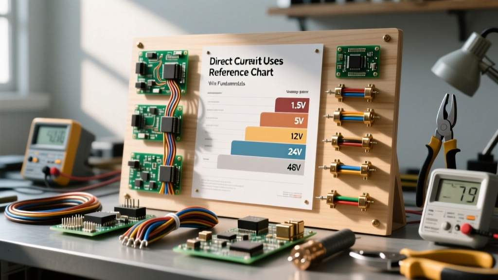
One of the most common mistakes beginners make when transitioning from AC household wiring to DC projects is underestimating voltage drop. Because most DIY DC systems operate at low voltages (12V, 24V, or 48V), even a small loss of voltage across a wire represents a massive percentage of the total system power.
For example, losing 2 volts on a 120V AC circuit is negligible (a 1.6% drop). But losing 2 volts on a 12V DC solar circuit means your charge controller is only seeing 10V, which may prevent your battery bank from charging entirely. Furthermore, the missing voltage is dissipated as heat in the wire, creating a fire hazard.
Calculating DC Voltage Drop
To size your wires correctly, you must use the voltage drop formula: V = I × R (Voltage Drop = Current × Resistance). Let us look at a real-world scenario:
- System: 12V DC LED light bar drawing 10 Amps.
- Wire Length: 20 feet total (10 feet positive, 10 feet negative).
- Wire Gauge: 14 AWG Copper (Resistance is approximately 2.525 ohms per 1,000 feet).
The Math: 20 feet of 14 AWG wire has a resistance of roughly 0.05 ohms.
10 Amps × 0.05 ohms = 0.5V drop.
Your lights will receive 11.5V. This is generally acceptable (under a 3% drop). However, if you used thin 18 AWG wire, the resistance would jump, the voltage drop would exceed 1.5V, and the wire could overheat.
Always consult a comprehensive wire sizing chart and use 10 AWG or thicker for high-current 12V DC runs. For deeper insights into electrical safety standards and wire ampacities, refer to the National Electrical Code (NFPA 70).
Polarity and Color Coding Standards
Because DC flows in only one direction, polarity is absolute. Reversing the positive and negative connections in an AC circuit usually does not matter (like plugging a lamp in upside down). In a DC circuit, reversing polarity can instantly destroy sensitive components, fry microcontrollers, or cause lithium battery management systems (BMS) to short out.
In standard DC wiring practices:
- Red wire is used for the Positive (+) ungrounded conductor.
- Black wire is used for the Negative (-) grounded conductor.
- White or Gray is sometimes used for a grounded DC conductor in specific high-voltage solar arrays, per NEC guidelines, but Red/Black remains the standard for 12V/24V DIY and automotive applications.
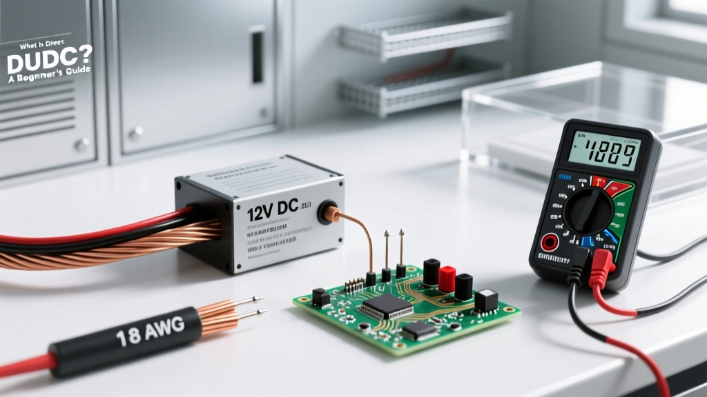
Pro-Tip: Always verify polarity with a digital multimeter set to DC Voltage (V⎓) before connecting a new power supply to a breadboard or microcontroller. A reading of negative voltage (e.g., -12V) on your multimeter simply means your red probe is on the negative terminal and your black probe is on the positive.
The Danger of DC Arcing: Why Switch Ratings Matter
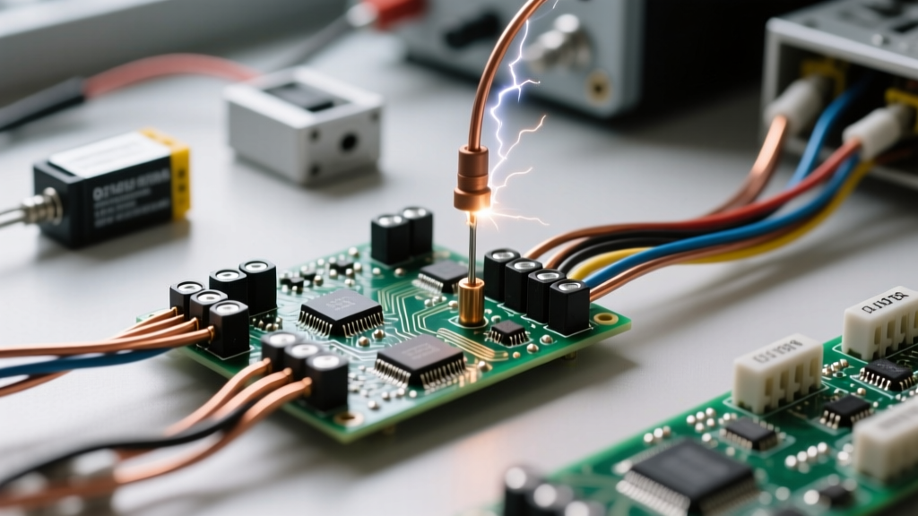
A critical safety concept often taught in advanced electrical fundamentals is the danger of DC arcing. When you open a mechanical switch or a circuit breaker while current is flowing, the electricity attempts to jump the gap between the separating metal contacts, creating a superheated plasma arc.
In an AC circuit, the voltage crosses zero 120 times a second. Every time it hits zero, the arc naturally extinguishes. DC voltage never crosses zero. Therefore, a DC arc will sustain itself, stretching out and potentially melting the switch contacts, causing a fire, or destroying the component. This is why you must never use a standard 120V AC household light switch to control a high-amperage 12V DC circuit. You must use switches and breakers specifically rated for DC voltage (often marked as VDC), which feature internal magnets or specialized spring mechanisms to physically blow the arc out and break the circuit safely.
Summary: Mastering DC for Your Projects
Understanding what is direct current goes far beyond a simple textbook definition. It requires respecting the unidirectional flow of electrons, meticulously calculating wire gauge to prevent low-voltage drop, adhering to strict polarity color codes, and utilizing DC-rated safety components to manage arcing. Whether you are building an off-grid solar array, wiring a custom PC water-cooling loop, or designing an Arduino-based sensor network, mastering these DC fundamentals is the bedrock of reliable and safe electrical engineering.
For further reading on electron flow and circuit theory, the All About Circuits DC Textbook is an exceptional, free resource for expanding your foundational knowledge.