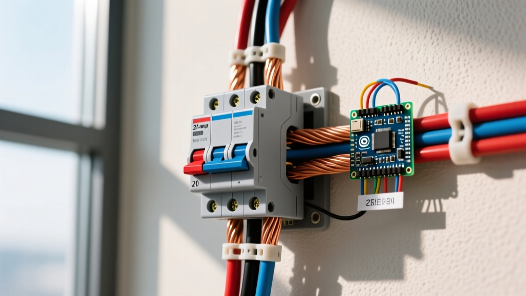
The National Electrical Code (NEC) 210.19(A) Informational Note No. 4 recommends a maximum voltage drop of 3% for branch circuits and 5% for the combined feeder and branch circuit. While not always a strictly enforceable violation in every local jurisdiction, ignoring NEC voltage drop guidelines leads to dim lights, tripped breakers from motor inrush, and overheated conductors. The direct answer for a 120V, 15A branch circuit is that you must keep your drop under 3.6V (3%).
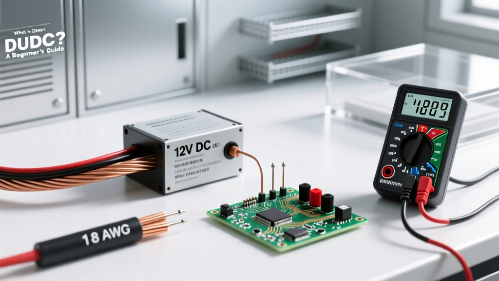
Rather than guessing or relying on cheap plastic pocket calculators, we are going to build a bench-top ESP32 dual-point voltage drop logger. This device measures actual source voltage, load voltage, and current draw in real-time. Safety Caveat: To maintain strict bench safety and avoid mains electrocution hazards, this build uses a 12V DC power supply to simulate the resistance of the wire run. The ESP32 firmware then applies standard copper resistance math to calculate the equivalent 120V AC drop percentage based on the ESP32's ADC and I2C sensor data.
Hardware BOM and Pin Mapping
This build targets the ESP32-WROOM-32 DevKit v1 (38-pin variant). Do not use the 30-pin variant without adjusting the SDA/SCL pin definitions, as the physical pinout shifts. We use INA219 high-side current/voltage sensors because they offer 12-bit ADC resolution, vastly outperforming the ESP32's internal non-linear ADC for precision millivolt drop measurements.
| Component | Exact Variant / Model | Quantity |
|---|---|---|
| Microcontroller | ESP32-WROOM-32 DevKit v1 (38-pin) | 1 |
| Sensor (Source) | INA219 I2C Breakout (Default Addr 0x40) | 1 |
| Sensor (Load) | INA219 I2C Breakout (Addr 0x41 via A0 jumper) | 1 |
| Display | 2004 (20x4) I2C LCD with PCF8574 backpack | 1 |
| Power Supply | 12V DC 5A LED Driver (Mean Well or similar) | 1 |
| Test Wire | 100 ft spool of 14 AWG or 12 AWG stranded copper | 1 |
ESP32 38-Pin Wiring Map
| ESP32 Pin | Target Component | Function |
|---|---|---|
| 3V3 | INA219 (x2) VCC, LCD VCC | Logic Power |
| GND | All GND pins | Common Ground |
| GPIO 21 | INA219 (x2) SDA, LCD SDA | I2C Data |
| GPIO 22 | INA219 (x2) SCL, LCD SCL | I2C Clock |
| VIN (5V) | LCD VDD (Backlight) | 5V Backlight Power |
0x40. You MUST bridge the 'A0' address jumper pad with solder on the Load-side INA219 to shift its address to 0x41. If you skip this, the I2C bus will collide and the code will halt.
Wiring the Dual-Point Voltage Drop Tester
Follow these numbered steps to assemble the bench tester. Remember, we are wiring the INA219 sensors in series with the load to measure the high-side voltage and current.
- Prepare the Source Sensor: Connect the 12V DC power supply positive output to the
VIN+screw terminal on INA219_A (Source). Connect the power supply negative to your common ground bus. - Wire the Test Spool: Connect a jumper wire from
VIN-on INA219_A to one end of your 100ft test wire spool. - Prepare the Load Sensor: Connect the other end of the 100ft test wire spool to the
VIN+screw terminal on INA219_B (Load). - Connect the Dummy Load: Connect a 12V DC load (like a 50W halogen bulb or high-power resistor) between
VIN-on INA219_B and the common ground bus. This completes the circuit. - Verify I2C Pull-ups: Most Adafruit/generic INA219 breakouts include 10k pull-up resistors on SDA/SCL. If your LCD backpack lacks them, add 4.7k resistors between GPIO 21/22 and 3V3.
- Power Up: Plug the ESP32 into your PC via USB. Do not energize the 12V supply until the firmware is flashed and the Serial monitor is open.
The Firmware: ESP32 C++ Code with Error Handling
This code requires the Adafruit_INA219 and LiquidCrystal_I2C libraries installed via the Arduino Library Manager. It includes explicit error handling for I2C initialization failures and calculates the equivalent 120V AC branch circuit drop based on the measured wire resistance.
#include <Wire.h>
#include <Adafruit_INA219.h>
#include <LiquidCrystal_I2C.h>

// Pin Definitions for ESP32-WROOM-32 (38-pin)
#define SDA_PIN 21
#define SCL_PIN 22

// I2C Addresses
#define INA219_A_ADDR 0x40 // Source side
#define INA219_B_ADDR 0x41 // Load side (A0 jumper bridged)
#define LCD_ADDR 0x27      // Standard PCF8574 address

Adafruit_INA219 ina_A(INA219_A_ADDR);
Adafruit_INA219 ina_B(INA219_B_ADDR);
LiquidCrystal_I2C lcd(LCD_ADDR, 20, 4);

// Constants for NEC Calculation Proxy
const float NOMINAL_AC_VOLTAGE = 120.0; // 120V AC Branch Circuit
const float MAX_BRANCH_DROP_PCT = 3.0;  // NEC 210.19(A) Info Note 4

void setup() {
  Serial.begin(115200);
  Wire.begin(SDA_PIN, SCL_PIN);

  lcd.init();
  lcd.backlight();
  lcd.setCursor(0, 0);
  lcd.print("Initializing I2C...");

  // Error Handling: Source Sensor
  if (!ina_A.begin(&Wire)) {
    Serial.println("Failed to find INA219 chip (Source 0x40)");
    lcd.clear();
    lcd.print("ERR: INA219_A 0x40");
    while (1) { delay(10); }
  }

  // Error Handling: Load Sensor
  if (!ina_B.begin(&Wire)) {
    Serial.println("Failed to find INA219 chip (Load 0x41)");
    lcd.clear();
    lcd.print("ERR: INA219_B 0x41");
    while (1) { delay(10); }
  }

  lcd.clear();
  lcd.print("Sensors OK. Ready.");
  delay(1500);
}

void loop() {
  // Read Source (Panel equivalent)
  float v_source = ina_A.getBusVoltage_V();
  float current_A = ina_A.getCurrent_mA() / 1000.0;

  // Read Load (Receptacle equivalent)
  float v_load = ina_B.getBusVoltage_V();

  // Calculate actual DC drop and wire resistance
  float v_drop_dc = v_source - v_load;
  float wire_resistance = (current_A > 0.05) ? (v_drop_dc / current_A) : 0.0;

  // Extrapolate to 120V AC equivalent drop at 15A
  float simulated_15a_drop = wire_resistance * 15.0;
  float drop_percentage = (simulated_15a_drop / NOMINAL_AC_VOLTAGE) * 100.0;

  // Output to Serial
  Serial.printf("V_Src: %.2fV | V_Load: %.2fV | I: %.2fA\n", v_source, v_load, current_A);
  Serial.printf("Wire R: %.3f ohms | Sim 15A Drop: %.2f%%\n", wire_resistance, drop_percentage);

  // Output to LCD
  lcd.clear();
  lcd.setCursor(0, 0);
  lcd.printf("Src:%.2fV Ld:%.2fV", v_source, v_load);
  lcd.setCursor(0, 1);
  lcd.printf("Curr: %.2fA R:%.3f", current_A, wire_resistance);
  lcd.setCursor(0, 2);
  lcd.printf("Sim 120V@15A Drop:");
  lcd.setCursor(0, 3);

  if (drop_percentage <= MAX_BRANCH_DROP_PCT) {
    lcd.printf("%.2f%% [PASS]", drop_percentage);
  } else {
    lcd.printf("%.2f%% [FAIL]", drop_percentage);
  }

  delay(1000);
}
Debugging: Sensor Collisions and Drift
When working with I2C sensors on the ESP32, the most common roadblock is bus initialization failure. If your Serial monitor outputs the exact error string: Failed to find INA219 chip, follow this ranked cause list.
The First 3 Things to Check
- I2C Address Collision (90% of failures): The Adafruit library defaults to pinging
0x40. If you forgot to solder the A0 jumper on the second INA219 board, both sensors are fighting for the same address. The ESP32 will fail to initialize the second instance. Fix: Unplug power, bridge the A0 pad on the load-side sensor with a drop of solder, and verify with an I2C scanner sketch. - Missing Pull-Up Resistors: The ESP32's internal pull-ups are weak (approx 45k ohms). The INA219 breakouts usually have 10k pull-ups, but if you are using cheap clones, they might be missing. Fix: Add external 4.7k resistors between SDA/SCL and 3.3V.
- Power Rail Starvation: The ESP32 DevKit v1's onboard 3.3V regulator can overheat if the LCD backlight draws too much current alongside the sensors, causing a brownout that resets the I2C peripheral. Fix: Power the LCD backlight (VDD) from the 5V VIN pin, not the 3V3 pin.
Decision Tree: Sizing Wire Based on Tester Output
Once your tester is running, use this decision path to make your final wire purchasing decision for a standard 120V, 15A branch circuit. This terminates in a concrete material pick.
| Tester Output (Sim 15A Drop) | NEC Status | Action Required |
|---|---|---|
| < 3.0% | Passes Branch & Feeder | Keep current wire gauge. |
| 3.1% - 5.0% | Fails Branch, Passes Total | Acceptable ONLY if this is a feeder + branch combined run. Reject for dedicated branch. |
| > 5.0% | Fails All NEC Guidelines | Upsize wire immediately. Risk of voltage sag and heat buildup. |
Extending and Simplifying the Build
Depending on your jobsite needs, you can easily modify this baseline architecture.
- How to Extend (Data Logging): Add a MicroSD card breakout (wired to SPI: GPIO 18, 19, 23, 5) and use the
SD.hlibrary to log timestamped voltage drop data. This is invaluable for generating compliance reports for solar array wire runs or long HVAC thermostat feeds. - How to Simplify (Headless Mode): If you don't want to carry an LCD, strip out the
LiquidCrystal_I2Clibrary entirely. Rely on the Serial output and use the ESP32's Bluetooth Low Energy (BLE) capabilities to stream thedrop_percentagevariable directly to a smartphone serial terminal app while you stand at the far end of the wire run.